[0016]The sandwich anti-vibration mount will restrain tangential deflection of the stator while still achieving a low-stiffness suspension in the radial direction. In other words, the sandwich anti-vibration mount will not restrain radial deflection of the stator to any practical extent, thereby minimising the transfer of forces from the stator into the external support frame.
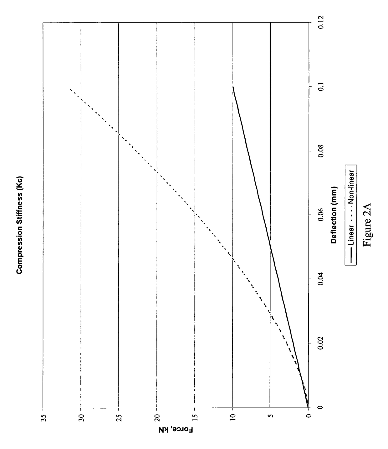
[0018]The sandwich anti-vibration mount is pre-loaded with a predetermined compression load. Any additional compression loads that might be applied to the sandwich anti-vibration mount will preferably not exceed about 60% of the pre-load. In other words, the pre-load Fp will generally be the dominant compression load that is applied to the sandwich anti-vibration mount throughout its operating lifetime. The pre-load is a static compression load and may be applied by any suitable mechanical means such as a through bolt or a shaped bracket, for example. The pre-load is applied along the compression axis of the sandwich anti-vibration mount. The application of the pre-load compresses the elastomeric layers of the sandwich anti-vibration mount and causes the rigid end support members to move closer together. Pre-loading the sandwich anti-vibration mount extends its service life by not allowing it to go through zero stress under normal operating conditions and generally increases the compression stiffness characteristic Kc. This means that deflections of the stator due to torque, shock etc. are reduced. Pre-loading also means that the performance of the sandwich anti-vibration mount is made substantially independent of the stator mass so that a standard sandwich anti-vibration mount can be used for any particular stator. This leads to a modular design of sandwich anti-vibration mount that is cost-effective to manufacture and is simple and easy to install to any stator support or frame.
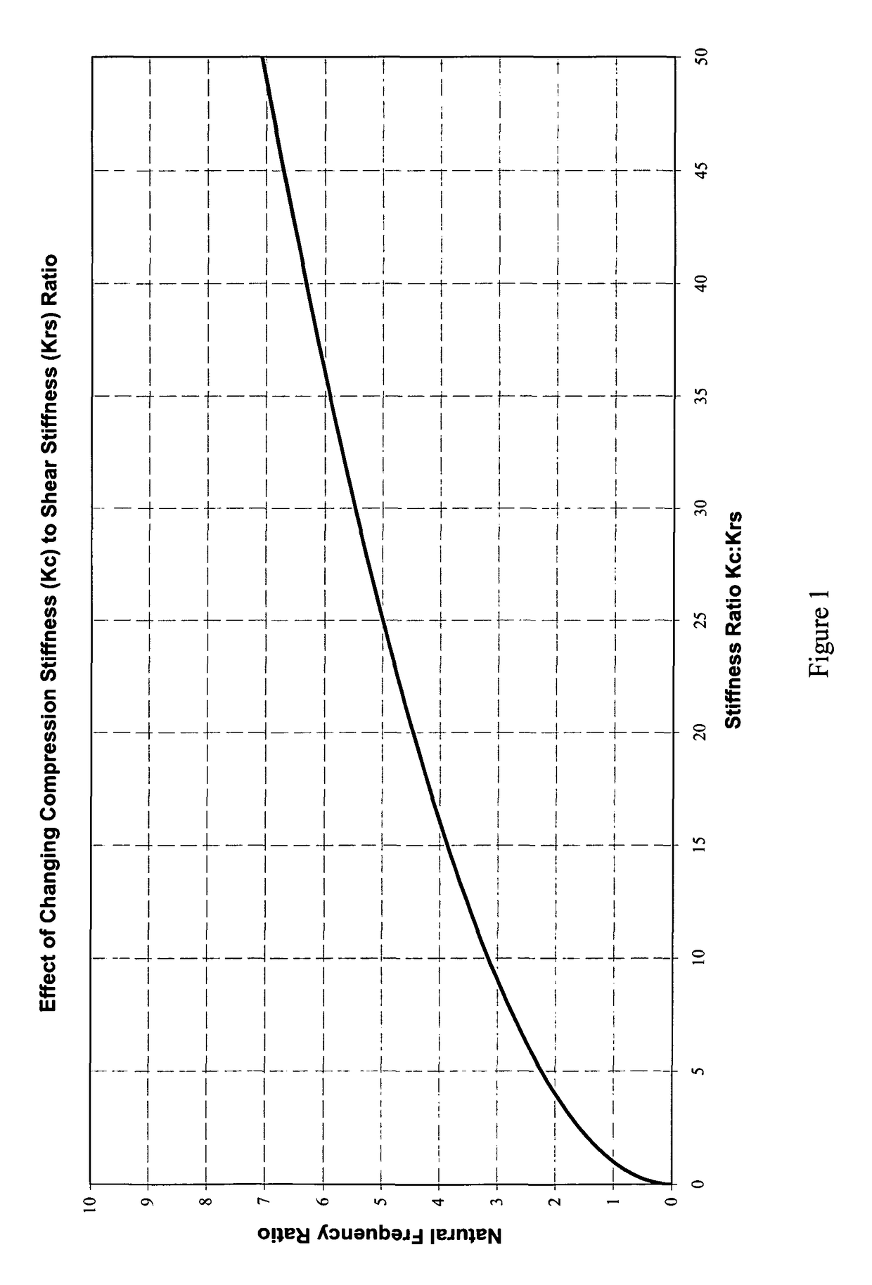
[0019]Pre-loading the sandwich anti-vibration mount also helps to reduce the radial shear stiffness characteristic Krs as a result of the Euler buckling effect. In other words, the radial shear stiffness characteristic Krs will reduce according to the amount of compression loading until it is substantially zero, or even negative, as the mount becomes unstable. Therefore, a sandwich anti-vibration mount having regressive radial shear stiffness characteristics versus compression loading, and hence an instability in the radial shear direction, provides significantly better vibration isolation. The physical design of the sandwich anti-vibration mount may play a part in achieving the desired radial shear stiffness characteristics (as described below) but since the pre-load is the dominant compression load that is applied to the mount during its operating lifetime then it is typically the amount of pre-load that is selected to provide a radial shear stiffness characteristic Krs that is substantially zero or negative. Such a radial shear stiffness characteristic is normally actively avoided for conventional sandwich anti-vibration mounts, e.g. of the type that are designed to be located underneath diesel engines or generator sets to provide a resilient suspension, because of the inherent instability that is known to arise. Excessive pre-load is also normally actively avoided because it can lead to problems such as creep, settlement and misalignment. In the case of the present invention, the instability that comes from having a radial shear stiffness characteristic Krs that is close to zero or negative is deliberately exploited to minimise the transfer of vibrations between the stator and the external support frame.
[0038]The sandwich anti-vibration mount has a high compression stiffness characteristic Kc and can therefore cope with significant levels of compression loading. However, the sandwich anti-vibration mount has a low radial shear stiffness characteristic Krs. In practice, it is generally preferred that the radial shear stiffness characteristic Krs is substantially zero, or even negative, to minimise the forces that are transferred into the external support frame as a result of stator electromagnetic forces. This in turn minimises the amount of noise that is emitted by the external support frame. It is believed that while a conventional support structure using springs might be capable of achieving a 20-30 dB noise reduction over the frequency range 10 Hz to 2 kHz, the improved support structure of the present invention might achieve a 50-70 dB noise reduction over the same frequency range. It will be readily appreciated that this is close to an ideal mass-less spring characteristic.
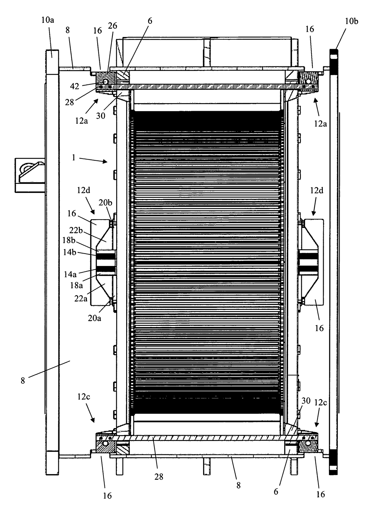
[0044]The elastomeric layers and interleaved rigid plates can be located between rigid end support members. One of the end support members can be used to locate the sandwich anti-vibration mount to a part of the stator while the other end support member can be used to locate the sandwich anti-vibration mount to the external support frame. In this way, the stator is effectively decoupled from the external support frame and it is only indirectly connected to it by means of the sandwich anti-vibration mount. The rigid end support members can be mechanically secured to the stator and external support frame using any suitable fixing such as bolts, for example, or may simply be positioned in or against a suitably shaped and sized seating provided at the stator and external support frame, respectively. Relative movement between the end support members in the tangential direction is experienced by the sandwich anti-vibration mount as a compression load while relative movement between the end support members in the radial direction is experienced by the sandwich anti-vibration mount as a radial shear load. In the case of a co-located pair of sandwich anti-vibration mounts then a single rigid end support member can be provided and shared by both mounts. For example, each sandwich anti-vibration mount may have a rigid end support member that locates the associated mount to the external support frame and a shared rigid end support member, positioned between them, that locates the mounts to a part of the stator.

