Horn antenna with a composite emitter for a radar-based level measurement system

a technology of radar-based level measurement and composite materials, which is applied in the direction of waveguide horns, instruments, and reradiation, etc., can solve the problems of high corrosive and highly aggressive chemicals in the material itsel

Active Publication Date: 2009-10-13
SIEMENS AG
View PDF40 Cites 6 Cited by
  • Summary
  • Abstract
  • Description
  • Claims
  • Application Information

AI Technical Summary

Problems solved by technology

Furthermore, the material itself may comprise highly aggressive (i.e. highly corrosive) chemicals or substances.

Method used


Image

  • Horn antenna with a composite emitter for a radar-based level measurement system
  • Horn antenna with a composite emitter for a radar-based level measurement system
  • Horn antenna with a composite emitter for a radar-based level measurement system

Examples


Embodiment Construction

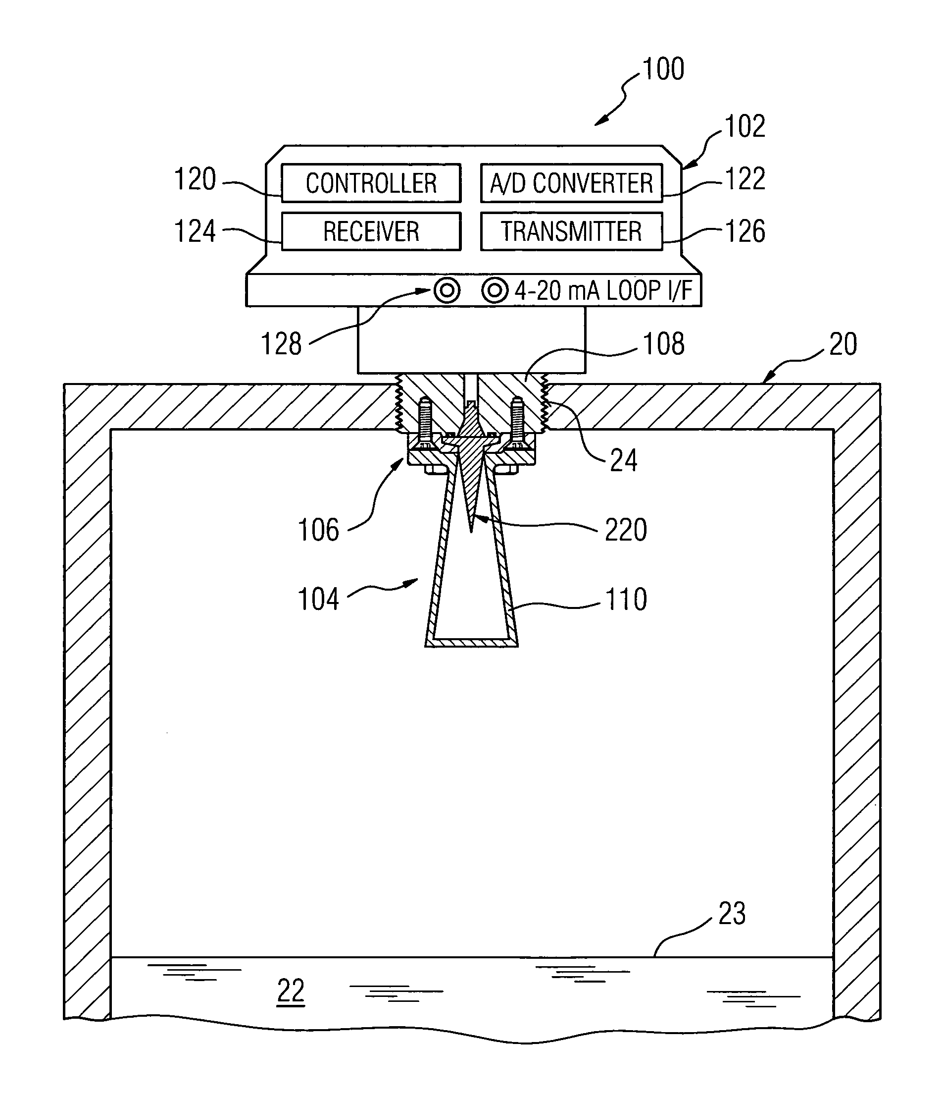
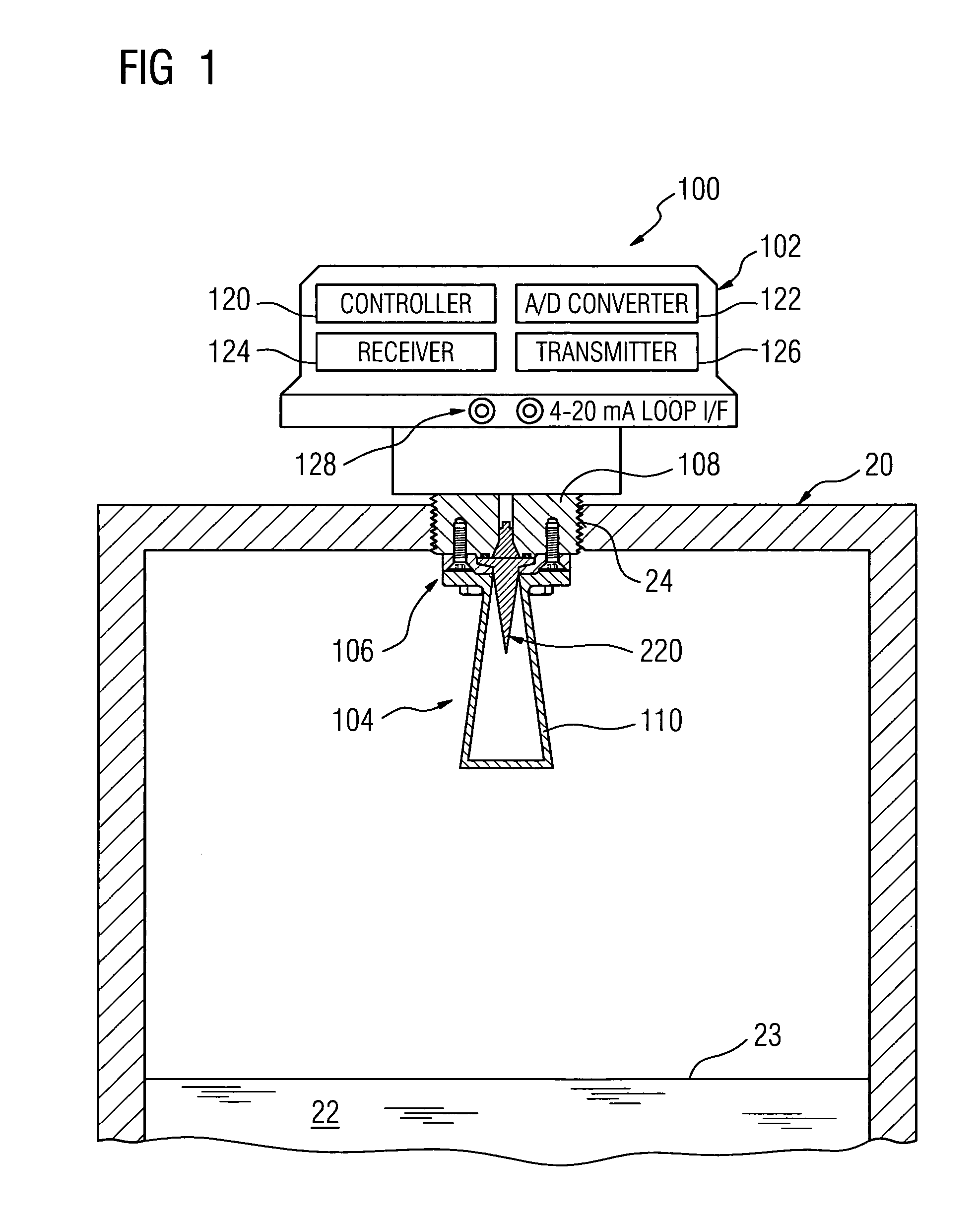
[0017]Reference is first made to FIG. 1 which shows in diagrammatic form a radar-based or a microwave-based level measurement apparatus 100 with a horn antenna having an emitter structure in accordance with the present invention.

[0018]As shown in FIG. 1, the level measurement apparatus 100 is mounted on top of a container or vessel 20 which holds a material 22, e.g. liquid, slurry or solid. The level measurement apparatus 100 functions to determine the level of the material 22 held in the vessel 20. The level of the material 20 is defined by a top surface, denoted by reference 23, which provides a reflective surface for reflecting electromagnetic waves or energy pulses. The vessel or container 20 has an opening 24 for mounting the level measurement apparatus 100.

[0019]The level measurement apparatus 100 comprises a housing member or enclosure 102, an antenna assembly 104 and a mounting mechanism 106. The housing 100 holds electrical / electronic circuitry as described in more detail b...


PUM


Abstract

A horn antenna suitable for use with a level measurement device and having a composite emitter structure. The emitter structure or assembly comprises an emitter and a plug. The emitter provides the process interface and is formed from a material having properties which include microwave transparency, chemical resistance and / or mechanical strength. The plug is isolated or partitioned from the process interface. The plug is formed from a material different from the emitter and exhibits the properties of microwave transparency and / or mechanical strength. According to another aspect, the level measurement device includes a coupling mechanism which allows the removal of the horn antenna independently of the emitter.

Description

CROSS REFERENCE TO RELATED APPLICATIONS[0001]This application claims priority of European application No. 05012669.7 EP filed Jun. 13, 2005, which is incorporated by reference herein in its entirety.FIELD OF THE INVENTION[0002]The present invention relates radar-based level measurement systems, and more particularly to a horn antenna arrangement having a composite material emitter.BACKGROUND OF THE INVENTION[0003]Time of flight ranging systems find use in level measurements applications, and are commonly referred to as level measurement systems. Level measurement systems determine the distance to a reflective surface (i.e. reflector) by measuring how long after transmission energy, an echo is received. Such systems may utilize ultrasonic pulses, pulse radar signals, or other microwave energy signals.[0004]Pulse radar and microwave-based level measurement systems are typically preferred in applications where the atmosphere in the container or vessel is subject to large temperature ch...

Claims


Application Information

Patent Timeline
Patent Type & Authority Patents(United States)
IPC IPC(8): G01S13/08
CPCH01Q13/02H01Q1/225H01Q13/24
Inventor SERBAN, GABRIELSINGH, BALJINDER
Owner SIEMENS AG
Why Eureka
Try Eureka