Method for the manufacture of optical fibers and improved optical fibers

a technology of optical fibers and fibers, applied in the field of optical fiber transmission systems, can solve the problems of increasing data bit rate, increasing system cost, and overlap of optical data pulses traveling over long transmission lengths

Inactive Publication Date: 2009-10-13
FURAKAWA ELECTRIC NORTH AMERICA INC
View PDF1 Cites 5 Cited by
  • Summary
  • Abstract
  • Description
  • Claims
  • Application Information

AI Technical Summary

Benefits of technology

[0018]A variety of optical fiber refractive index profiles that produce these transmission characteristics may be designed. In prior art designs, these have a complex profile comprising six or more layers. The profile design of this invention is a simple four layer design comprising an up-doped central core (usually referred to as the core), surrounded by a down-doped region (usually referred to as the trench), further surrounded by an up-doped region (referred to as the ring), further surrounded by an essentially undoped cladding. A similar basic profile (but with different performance characteristics) is described and claimed in U.S. Pat. Nos. 5,878,182, and 5,905,838, which are incorporated herein by reference. In advanced DCF designs, the profile of the invention may also have a second down-doped trench, with a width of, for example, 2-10 microns, added either just outside the ring, or farther out in the cladding, in order to adjust the cutoff wavelength, and reduce microbending loss.

Problems solved by technology

This problem grows significantly as the data bit rate is increased.
When dispersion is severe, optical data pulses traveling over long transmission lengths may overlap.
These elements, referred to as Dispersion Compensating Fiber (DCF) are very effective, but add cost to the system.
Thus an optical fiber transmission line with high dispersion limits the distance that high bit rate signals can travel without expensive dispersion compensation.
On the other hand, too little dispersion allows adjacent signals to interfere and produce crosstalk.
However, it is known that even in state of the art systems having dispersion compensating elements, some residual dispersion exists in the demultiplexed channels.

Method used


Image

  • Method for the manufacture of optical fibers and improved optical fibers
  • Method for the manufacture of optical fibers and improved optical fibers
  • Method for the manufacture of optical fibers and improved optical fibers

Examples


Embodiment Construction

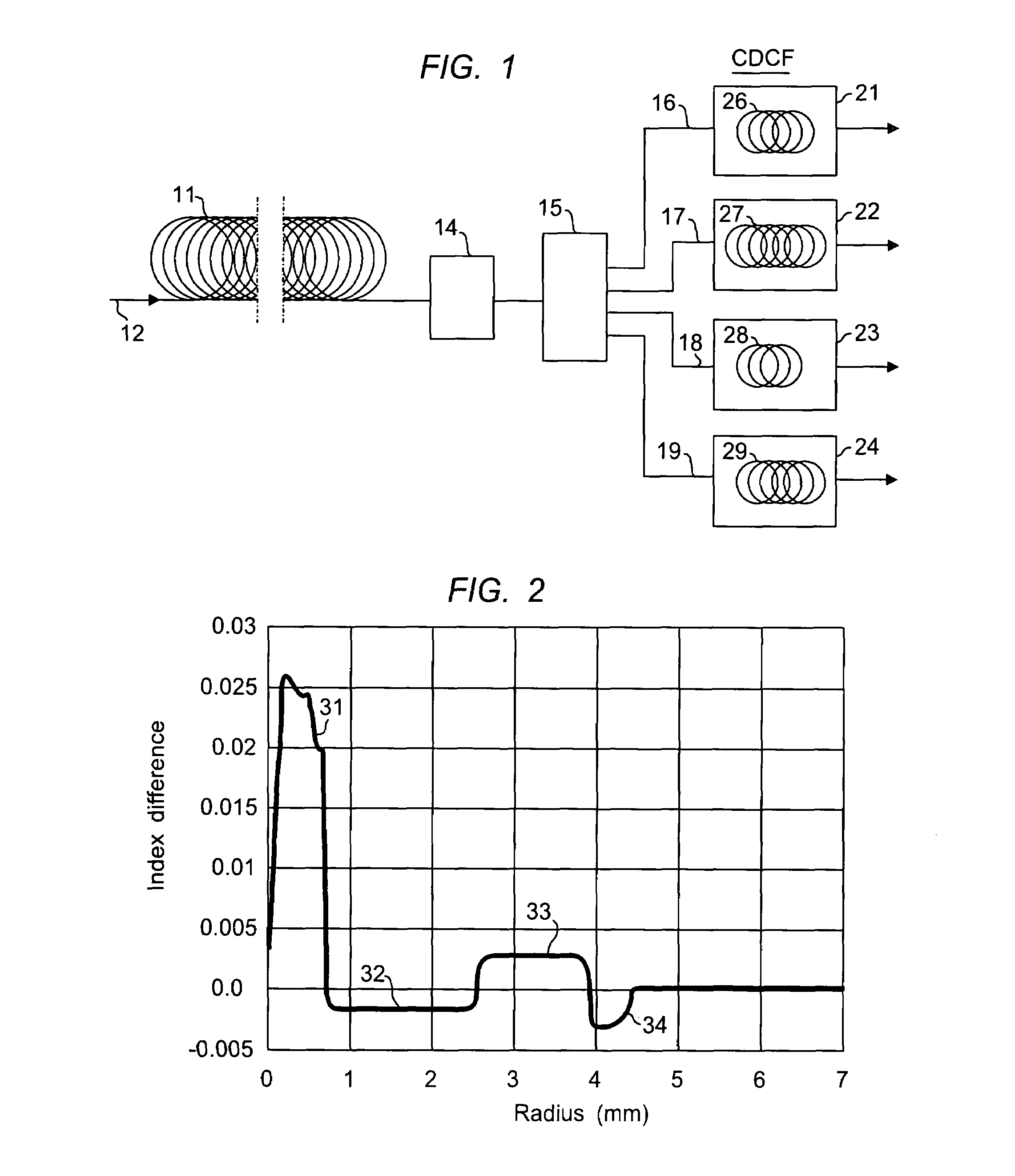
[0024]A long haul transmission system, with dispersion compensating and demultiplexing elements, is shown schematically in FIG. 1. Here the long length of transmission fiber is shown at 11, with input signal at 12. The transmission fiber 11 may be tens of kilometers in length. The input signal is a multiplexed signal, typically with at least 4 signal bands. In state-of-the-art systems, the input signal operates at 10 Gb or more, and has 8 or more channels, more typically 40 or more channels. In FIG. 1, the element that performs the transmission line compensation is represented by box 14. This element is typically installed in-line and may operate on the entire bandwidth of the multiplexed signal. In systems where the bandwidth is very wide, for example, in systems covering at least portions of the S-, C- and L-bands, the overall signal may be split into two or more bands, and a separate DCF is used for each of the split bands.

[0025]The dispersion compensated signal then arrives at t...


PUM

PropertyMeasurementUnit
wavelength regionaaaaaaaaaa
wavelengthaaaaaaaaaa
wavelengthsaaaaaaaaaa

Abstract

The present invention is directed to a universal channel dispersion compensating fiber (CDCF) for WDM channel compensation that provides essentially zero dispersion slope over the wide wavelength band used in state-of-the-art transmission systems. It allows compensation of a large number of channels using a single fiber design. The improved optical fiber of the invention exhibits a dispersion slope at 1550 nm: <0.02 ps / nm2-km, preferably <0.01 ps / nm2-km, and a maximum variation of dispersion per km over the S-, C-, and L- bands of preferably less than 2.0 ps. In a preferred embodiment, the index profile of these fibers comprises a simple three layer design, which includes an up-doped central core, surrounded by a down-doped trench region, further surrounded by an up-doped ring region.

Description

RELATED APPLICATION[0001]This application is a Division of application Ser. No. 10 / 426,193, filed Apr. 30, 2003 now abandoned.FIELD OF THE INVENTION[0002]This invention relates to optical fiber transmission systems having improved optical transmission characteristics, and in particular, systems using optical fiber with improved dispersion compensation.BACKGROUND OF THE INVENTION[0003]Optical transmission systems employ Wavelength Division Multiplexing (WDM) to increase information handling of an optical fiber transmission line, typically a long haul transmission line. Early WDM systems operated with a relatively narrow wavelength bandwidth, centered around 1550 nanometers, e.g. 1530-1565 nanometers, referred to as the C-band. This is the wavelength region where standard silica based optical fibers have optimally low absorption.[0004]In most WDM systems there is a trade-off between the number of channels the system accommodates and the channel separation. Higher bit rates generally c...

Claims


Application Information

Patent Timeline
Patent Type & Authority Patents(United States)
IPC IPC(8): G02B6/02
CPCG02B6/03666G02B6/02242G02B6/02261C03B2201/02C03B2201/12C03B2201/31C03B2203/22G02B6/03611C03B2203/36
Inventor RATHJE, JACOBGRUNER-NIELSEN, LARS
Owner FURAKAWA ELECTRIC NORTH AMERICA INC
Why Eureka
Try Eureka