Raman fiber amplifier communication systems

a technology of amplifiers and fibers, applied in the field of optical fibers, can solve the problems of increasing transmission errors, and difficult to reach the objective, and achieve the effects of reducing system cost and complexity, reducing system cost, and reducing system cos

Inactive Publication Date: 2005-08-04
KALISH DAVID +3
View PDF34 Cites 2 Cited by
  • Summary
  • Abstract
  • Description
  • Claims
  • Application Information

AI Technical Summary

Benefits of technology

[0023] A variety of optical fiber refractive index profiles that produce these transmission characteristics have been designed. In general these have a complex core comprising an up-doped central core (usually referred to as the core), surrounded by a down-doped region (usually referred to as the trench), further surrounded by an up-doped region (referred to as the ring). A similar basic profile (but with different performance characteristics) is described and claimed in U.S. Pat. No. 5,878,182, and U.S. Pat. No. 5,905,838, which are incorporated herein by reference. In advanced fiber designs, the profile may also have a second down-doped trench, width a width of, for example, 2-10 microns, added either just outside the ring, or farther out in the cladding, in order to adjust the cutoff wavelength, and reduce microbending loss.

Problems solved by technology

This objective becomes more difficult to reach as the operating wavelength range is extended to longer and / or shorter wavelengths.
However there is one persistent problem with multiple pumps.
In telecommunications systems, if FWM occurs in the signal band this can lead to transmission errors.
Moreover, to TDM a relatively large number of pump wavelengths, some operating at relatively high power, adds significantly to the cost and complexity of the system.
This problem grows significantly as the data bit rate is increased.
An optical transmission line, comprising a cabled fiber and a dispersion compensation element (typically a module but possibly a cabled fiber), that transmits effectively at 10 Gb / s may show excessive error rates at 40 Gb / s because of bit overlap.
A problem arises in designing optical fibers to meet this general need: typical optical fiber profiles that are optimized for low dispersion slope have reduced effective area due to bend loss constraints.
For Raman amplified systems, too small effective area exacerbates the issues of “Raman gain tilt” whereby shorter wavelength pumps (signals) transfer energy to longer wavelength pumps (signals).
Thus the manufacture of optical fibers for high bit rate (e.g. 40 Gb / s) systems and with both low dispersion slope and medium or large effective area, while at the same time preserving other performance characteristics such as low Polarization Mode Dispersion (PMD), is a design challenge.

Method used


Image

  • Raman fiber amplifier communication systems
  • Raman fiber amplifier communication systems
  • Raman fiber amplifier communication systems

Examples


Embodiment Construction

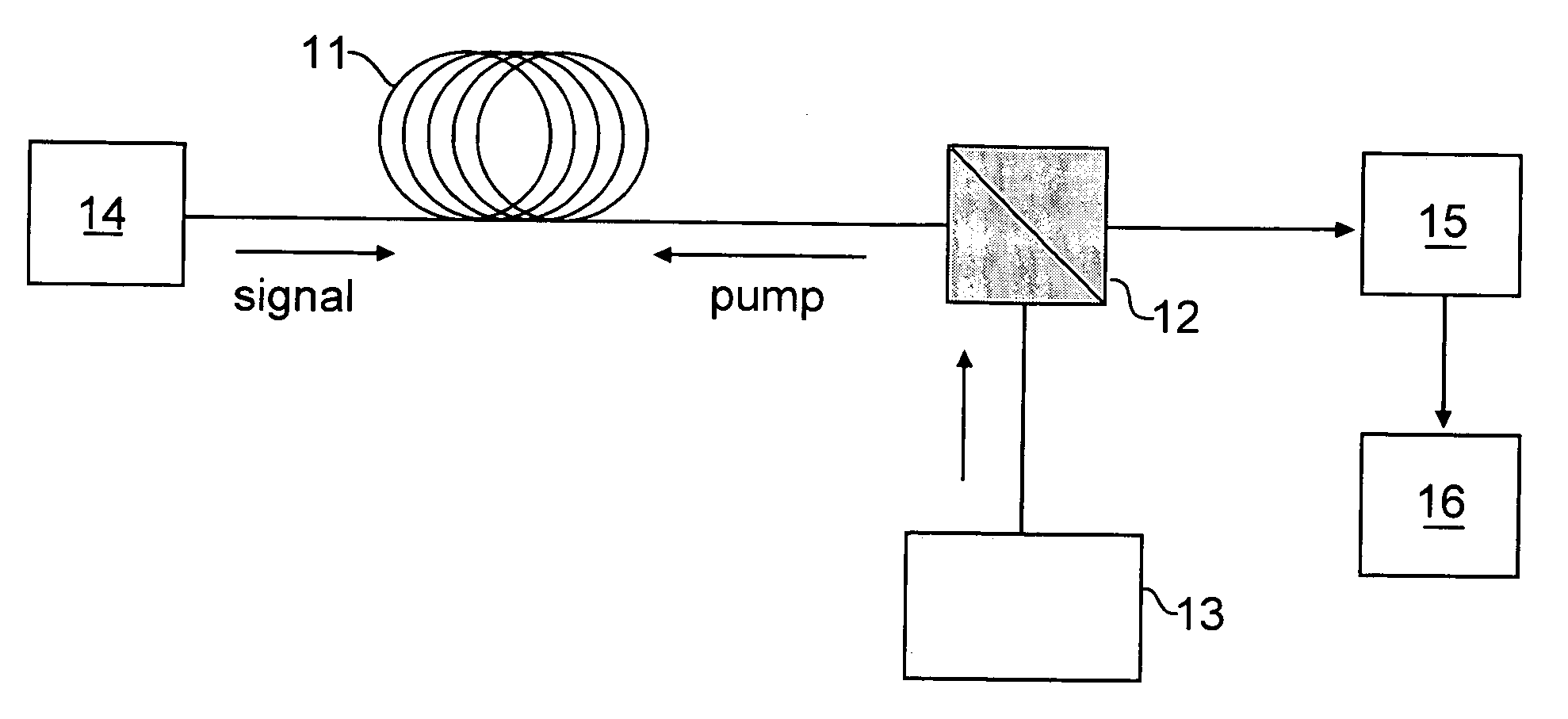
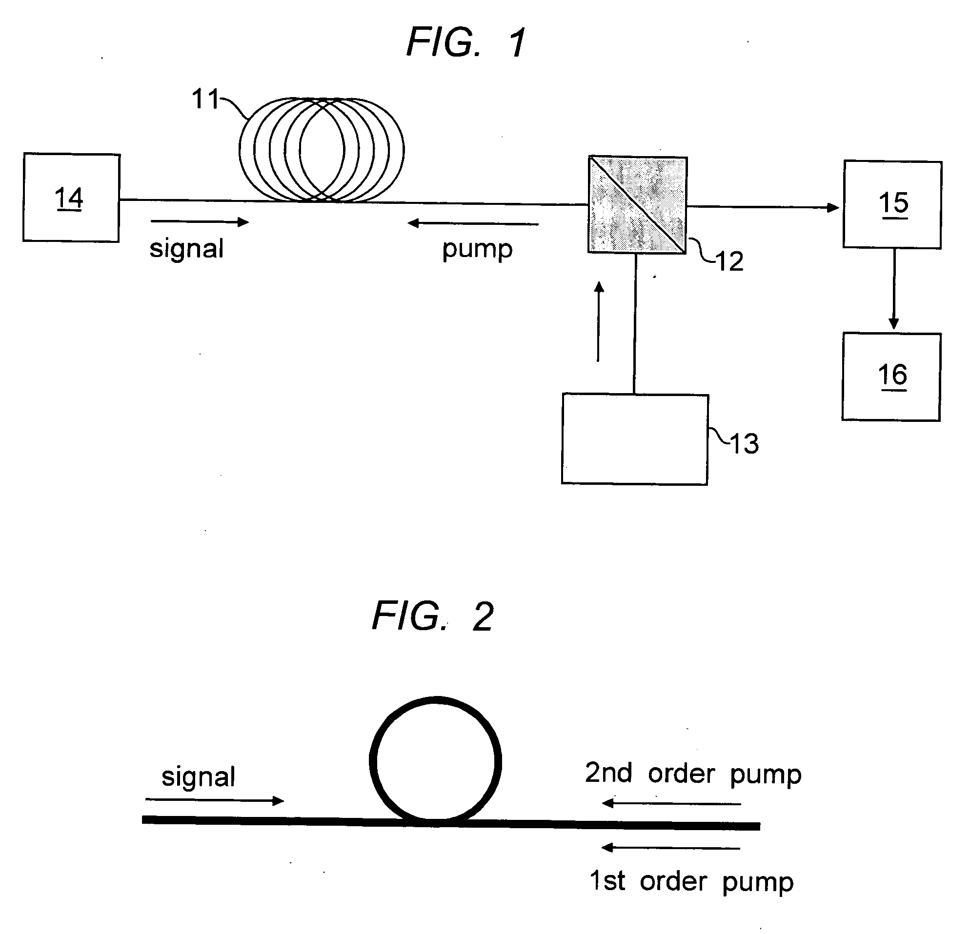
[0032] Referring to FIG. 1, an optical fiber communications system is shown with a distributed Raman optical fiber amplifier. The transmission span 11 represents a fiber of substantial length, typically in excess of 1 km. It will be evident to those skilled that the figures in this description are not drawn to scale, and the elements are schematically shown. For purposes of illustration, FIG. 1 shows a distributed amplifier where the amplifier medium is the normal transmission span. For discrete amplifiers, a dedicated length of optical fiber can be used for the amplification medium. The length of fiber represented by 11 is typically at least 500 m in length to allow for the optical interactions that produce signal amplification. The amplifier is end pumped, and counter pumped, as shown in the figure, by pump source 13 coupled into the core of the fiber through coupler shown schematically at 12. The system transmitter is shown at 14 and the system receiver at 16. A dispersion compen...


PUM

PropertyMeasurementUnit
areaaaaaaaaaaa
Cable cutoff wavelengthaaaaaaaaaa
wavelengthsaaaaaaaaaa

Abstract

The specification describes an improved optical fiber design in which the criteria for high performance in a Raman amplified optical system, such as moderate effective area, moderate dispersion, low dispersion slope, and selected zero dispersion wavelength, are simultaneously optimized. In preferred embodiments of the invention, the dispersion characteristics are deliberately made selectively dependent on the core radius. This allows manufacturing variability in the dispersion properties, introduced in the core-making process, to be mitigated during subsequent processing steps.

Description

RELATED APPLICATIONS [0001] This application is a continuation-in-part of application Ser. No. 10 / 353762, filed Jan. 29, 2003.FIELD OF THE INVENTION [0002] This invention relates to optical fibers having improved optical transmission characteristics, methods for their production, and communication systems incorporating the improved optical fibers. BACKGROUND OF THE INVENTION [0003] Optical transmission systems employ Wavelength Division Multiplexing (WDM) to increase information handling of an optical fiber transmission line, typically a long haul transmission line. Early WDM systems operated with a relatively narrow wavelength bandwidth, centered around 1550 nanometers, e.g. 1530-1565 nanometers, referred to as the C-band. This is the wavelength region where standard silica based optical fibers have optimally low absorption. [0004] In most WDM systems there is a trade-off between the number of channels the system accommodates and the channel separation. Higher bit rates generally c...

Claims


Application Information

Patent Timeline
Patent Type & Authority Applications(United States)
IPC IPC(8): C03B37/012G02B6/028G02B6/036
CPCC03B37/01228C03B2201/02C03B2201/12C03B2201/31C03B2203/22C03B2203/36G02B6/03644G02B6/02014G02B6/02242G02B6/02271G02B6/0281G02B6/03611G02B6/02009Y02P40/57C03B2203/23
Inventor KALISH, DAVIDKIM, JINKEELINGLE, ROBERT JR.QIAN, YIFEI
Owner KALISH DAVID
Why Eureka
Try Eureka