Efficiently finding shortest paths using landmarks for computing lower-bound distance estimates

a landmark and distance estimation technology, applied in the field of routing, can solve the problems of dijkstra's original method, which is not always efficient in practice, and the computation of the shortest path may require significant computational time and resources, and achieve the effect of reducing the amount of storag

Inactive Publication Date: 2009-10-13
MICROSOFT TECH LICENSING LLC
View PDF6 Cites 85 Cited by
  • Summary
  • Abstract
  • Description
  • Claims
  • Application Information

AI Technical Summary

Benefits of technology

[0005]Methods and systems are provided for computing shortest paths among a set of locations. A small set of landmarks is chosen and the distance between each location and each landmark is computed and stored. Given source and destination locations, the landmark distances are used to compute lower-bound estimates of distances from locations to the destination. The estimates are then used with a heuristic search to find the shortest path from source to destination. Additional improvements are provided to reduce the amount of storage required.
[0006]In one aspect, a computer-readable medium is provided including computer-executable instructions facilitating the finding of a shortest path from a starting location to a destination location among a set of locations, the computer-executable instructions performing the step of estimating distances to the destination location from locations in the set of locations by using distances between the locations and one or more landmarks from a set of landmarks.

Problems solved by technology

Computing the best-route between locations may require significant computational time and resources.
Dijkstra's original method, however, is not always efficient in practice, due to the large number of locations and possible paths that are scanned.
A good estimate reduces the number of locations and road segments that must be considered by the road-mapping program, resulting in a faster computation of shortest paths; a bad estimate can have the opposite effect, and increase the overall time required to compute shortest paths.
Lower-bounds that are very close to the actual values being bound are said to be “good.” Previously known heuristic variations use lower-bound estimation techniques such as Euclidean distance (i.e., “as the crow flies”) between locations, which are not very good.

Method used


Image

  • Efficiently finding shortest paths using landmarks for computing lower-bound distance estimates
  • Efficiently finding shortest paths using landmarks for computing lower-bound distance estimates
  • Efficiently finding shortest paths using landmarks for computing lower-bound distance estimates

Examples


Embodiment Construction

[0020]The methods and systems to compute shortest paths using landmarks to estimate distances will now be described with respect to preferred embodiments; however, the methods and systems of the present invention are not limited to computing shortest paths. Moreover, the skilled artisan will readily appreciate that the methods and systems described herein are merely exemplary and that variations can be made without departing from the spirit and scope of the invention.

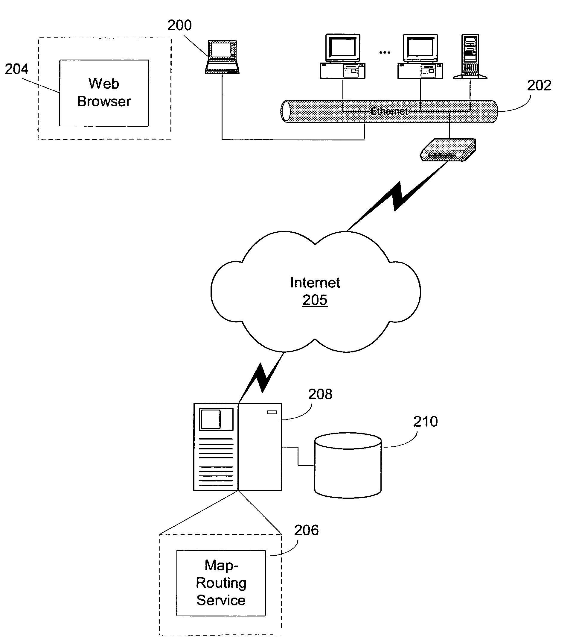
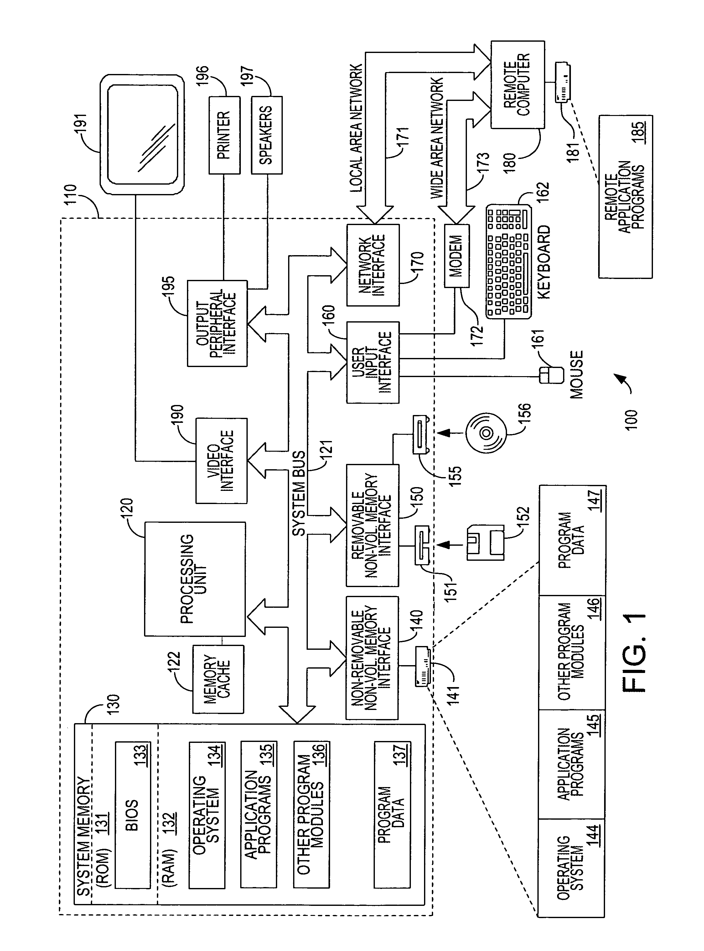
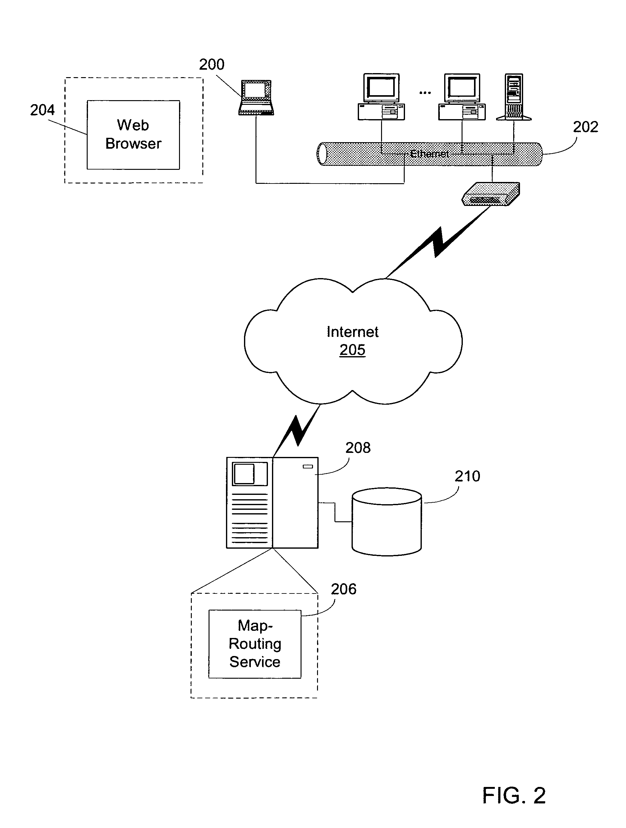
[0021]The present invention will be more completely understood through the following detailed description, which should be read in conjunction with the attached drawings. In this description, like numbers refer to similar elements within various embodiments of the present invention. The invention is illustrated as being implemented in a suitable computing environment. Although not required, the invention will be described in the general context of computer-executable instructions, such as procedures, being executed by a...


PUM


Abstract

Methods and systems are described for computing shortest paths among a set of locations. A small set of landmarks is chosen and the distance between each location and each landmark is computed and stored. Given source and destination locations, the landmark distances are used to compute lower-bound estimates of distances from locations to the destination. The estimates are then used with a heuristic search to find the shortest path from source to destination.

Description

FIELD OF THE INVENTION[0001]This invention pertains generally to the field of routing and more particularly to calculating a best route between two points on a computerized map.BACKGROUND OF THE INVENTION[0002]Existing computer programs known as “road-mapping” programs provide digital maps, often complete with detailed road networks down to the city-street level. Typically, a user can input a location and the road-mapping program will display an on-screen map of the selected location. Several existing road-mapping products typically include the ability to calculate a “best route” between two locations. In other words, the user can input two locations, and the road-mapping program will compute the travel directions from the source location to the destination location. The directions are typically based on distance, travel time, and certain user preferences, such as a speed at which the user likes to drive, or the degree of scenery along the route. Computing the best-route between loc...

Claims


Application Information

Patent Timeline
Patent Type & Authority Patents(United States)
IPC IPC(8): G01C21/34
CPCG01C21/34
Inventor GOLDBERG, ANDREW V.HARRELSON, CHRISTOPHER ROBERT
Owner MICROSOFT TECH LICENSING LLC
Why Eureka
Try Eureka