
Method and apparatus for creating support columns using a hollow mandrel with upward flow restrictors

a technology of restrictors and mandrels, which is applied in the direction of bulkheads/piles, construction, foundation engineering, etc., can solve the problems of material pushed up into the mandrel, achieve the effect of preventing upward flow of aggregate, facilitating the construction of stronger and stiffer piers, and clogging the mandrel

Active Publication Date: 2009-10-20
GEOPIER FOUND
View PDF14 Cites 31 Cited by
  • Summary
  • Abstract
  • Description
  • Claims
  • Application Information

AI Technical Summary

Benefits of technology

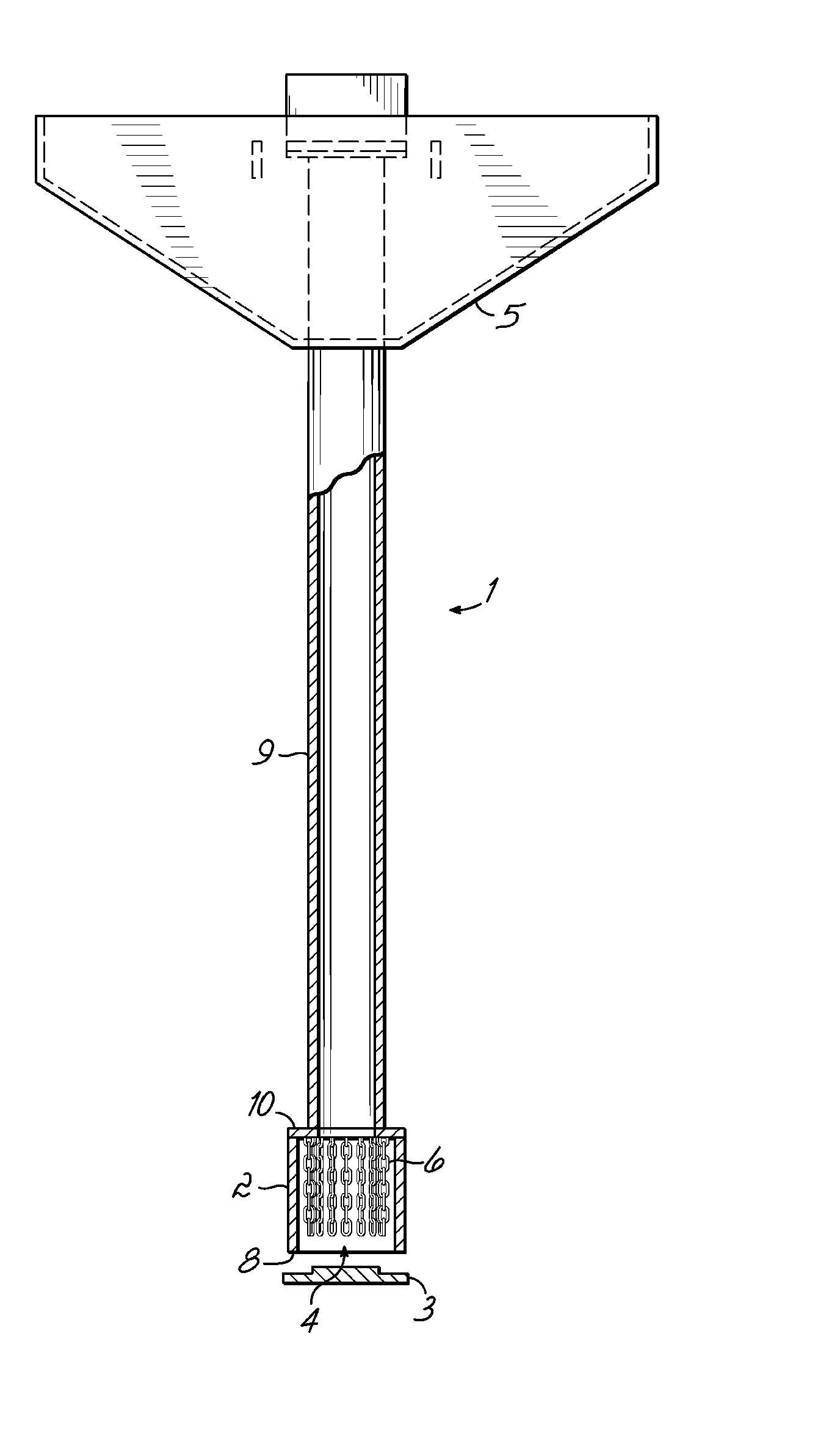
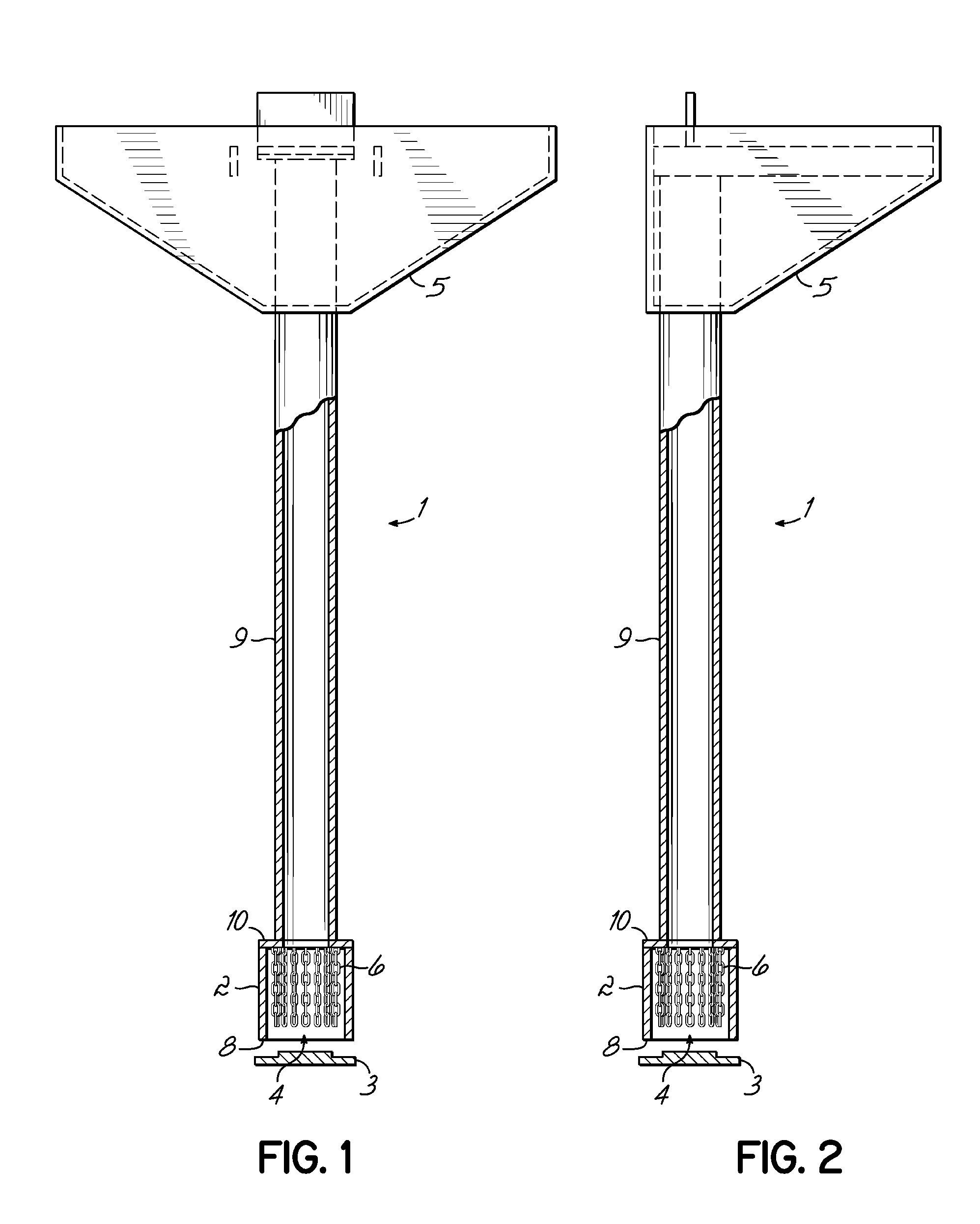
[0011]In one embodiment, the invention can employ two cylindrical pipe portions aligned with their adjacent ends interconnected to form an elongate mandrel. A top pipe portion of the mandrel is a primary aggregate delivery mechanism. Aggregate is fed into a hopper at the upper end of the top pipe portion. A bottom pipe portion of the mandrel can have a slightly larger diameter than the top pipe portion also operates as a tamper head for the mandrel. Structural members, which can be active mechanical or passive, are located within the bottom pipe portion. The structural members allow generally unrestricted movement of aggregate materials downward through the mandrel and out through the bottom pipe portion as the mandrel is lifted. When tamping of aggregate is conducted through the downward movement of the mandrel, the structural members restrict or retard the upward flow of aggregate or other materials into the mandrel.
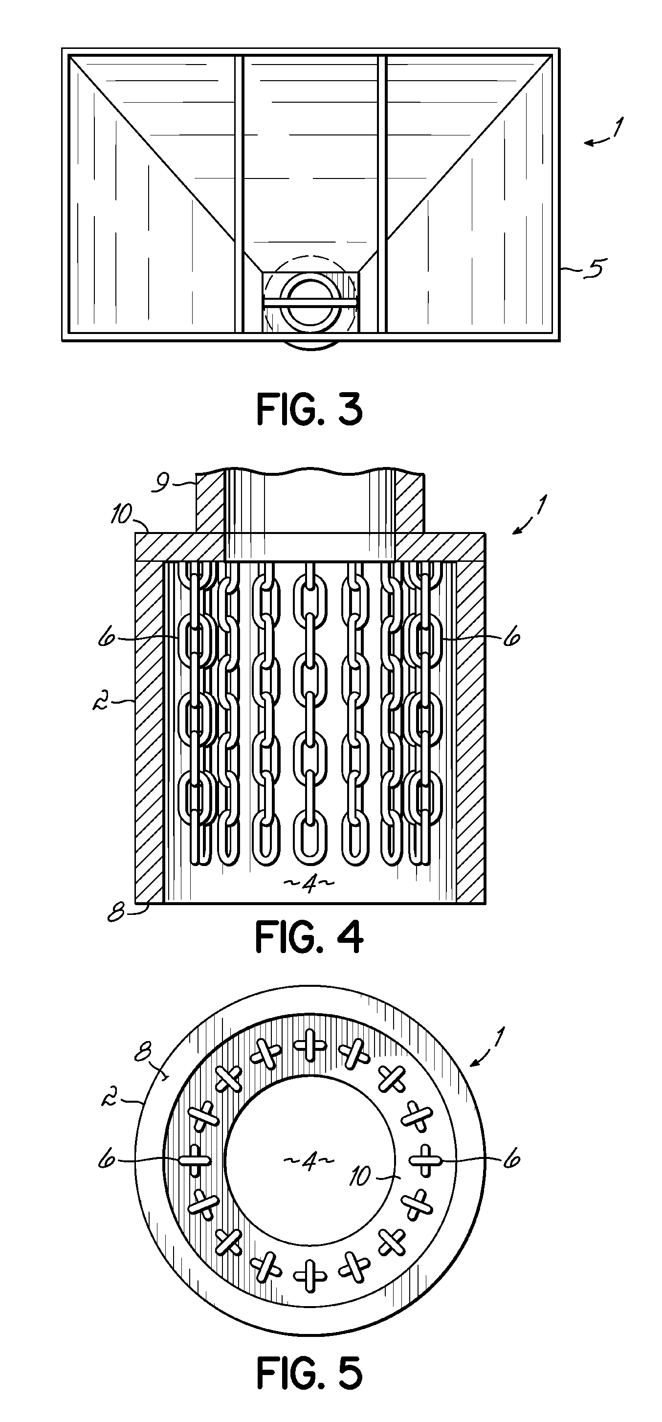
[0012]In a first embodiment, the bottom pipe portion includes mechanical flow restrictors, for example, in the form of movable vertically extending members. The restrictors are mounted near the top region on the interior of the bottom pipe portion, adjacent to the interface of the two pipe sections (although it is understood that the top and bottom portions could comprise a single unitary unit with varying wall thicknesses, etc.). The mechanical flow restrictors operate in an active and dynamic manner to restrict upward movement of aggregate or soil in the mandrel during tamping or compacting operations.
[0013]In this embodiment, the mechanical flow restrictors are preferably made up of steel chains, wire rope, or other like mechanisms. The mechanical flow restrictors are typically secured at their top end inside the mandrel bottom pipe portion or tamper head, and extend vertically downward within the mandrel bottom pipe portion as the mandrel is raised. This is because the aggregate straightens out the restrictors as the mandrel is lifted upward. When the mandrel is moved downward during aggregate compaction, the mechanical flow restrictors are free to move, and move inward and upward within the mandrel bottom pipe portion as a result of interaction with aggregate. When the restrictors move inward, they tend to bunch up the aggregate thus restricting upward flow of aggregate in the mandrel.
[0014]In a more specific embodiment, the lower end of the mandrel may also include a sacrificial plate (otherwise also referred to herein as a disposable driving shoe). The sacrificial plate is inserted into an opening at the bottom of the tamper head of the mandrel. The plate prevents soil from entering the mandrel during the driving operation and is left at the bottom of the mandrel during aggregate placement and compaction. Alternatively, the sacrificial plate may be eliminated and aggregate may be placed inside of the mandrel prior to driving. The aggregate serves to restrict soil from entering the mandrel during driving, as it is prevented from flowing back into the mandrel by the mechanical flow restrictors.
[0018]As with the first embodiment, the lower end of the mandrel may also be fitted with a sacrificial plate inserted into the opening at the bottom of the tamper head of the mandrel. In an alternative, the plate may be eliminated and aggregate placed in the mandrel prior to driving to prevent soil from entering during operation. During downward driving, aggregate entering the bottom of the mandrel is engaged by the passive restrictors. This action causes the aggregate between the passive restrictors to “arch” to the restrictors, thus “clogging” the mandrel and preventing upward flow of the aggregate.
[0019]The present invention in all embodiments permits unrestricted gravity flow or movement of the aggregate relative to the mandrel while raising the mandrel and provides for a mechanical or passive constriction that creates a temporary aggregate plug while driving the mandrel downward. The aggregate plug prevents further upward movement of the aggregate within the mandrel and thus allows the aggregate plug to be used as an additional compaction surface, along with the bottom edge of the tamper head, during downward ramming. This greater compaction surface facilitates the construction of stronger and stiffer piers.

Problems solved by technology

However, during compaction there is a possibility that materials may be pushed up into the mandrel as the mandrel is forced down.

Method used


Image

  • Method and apparatus for creating support columns using a hollow mandrel with upward flow restrictors
  • Method and apparatus for creating support columns using a hollow mandrel with upward flow restrictors
  • Method and apparatus for creating support columns using a hollow mandrel with upward flow restrictors

Examples


example

[0060]FIG. 18 shows test results for two piers, one constructed using a method similar to that described in U.S. Pat. No. 7,226,246 and one constructed using the invention. Both piers were built using mandrels with 14 inch diameter heads and using the 3 foot up and 2 foot down method (as described hereinabove). The graph of FIG. 18 shows that the pier constructed with a mandrel such as that of FIGS. 1-10 is stiffer than one constructed using a system such as that of U.S. Pat. No. 7,226,246. More particularly, the graph shows top-of-pier stress on the x-axis with top-of-pier deflection on the y-axis. Volume measurements made during construction showed that the average pier diameter using the system in accordance with the invention was 20% greater than that using the system of the referenced U.S. Patent.

[0061]In conducting the tests, the aggregate used for both systems for the modulus load test pier consisted of crushed limestone gravel having a nominal particle size ranging from abou...


PUM


Abstract

A system and method for installing aggregate piers is provided. A cylindrical hollow mandrel is driven to a desired depth. Aggregate is fed through the mandrel in steps. The mandrel is raised and driven to tamp the aggregate. Physical members in a tamping head of the mandrel allow aggregate to remain in a cavity formed by the mandrel, and prevent aggregate from entering the mandrel during driving.

Description

CROSS REFERENCE TO RELATED APPLICATIONS[0001]This application is related to and claims priority to U.S. Provisional Application Ser. No. 60 / 902,504, filed Feb. 22, 2007 and U.S. Provisional Application Ser. No. 60 / 902,861 filed Feb. 23, 2007. The disclosures of both referenced Provisional Applications are specifically incorporated by reference herein.FIELD OF THE INVENTION[0002]The present invention relates to the installation of aggregate piers in foundation soils for the support of buildings, walls, industrial facilities, and transportation-related structures, using displacement mandrels. In particular, the present invention is directed to methods and apparatus for the installation of aggregate piers through the use of a cylindrical hollow mandrel that includes arrangements for restricting the upward flow of aggregate into the mandrel during compaction.BACKGROUND OF THE INVENTION[0003]Heavy or settlement-sensitive facilities that are located in areas containing soft or weak soils ...

Claims


Application Information

Patent Timeline
IPC IPC(8): E02D3/12
CPCE02D3/08E02D5/44E02D5/36E02D3/12E02D5/34E02D5/62
Inventor WISSMANN, KORD J.METCALFE, BRIAN C.
Owner GEOPIER FOUND
Learn More