Thermosyphon cooling for overheat protection

a technology of overheating protection and thermal insulation, applied in the field of fluidic systems, can solve the problems of inability to use spring-type check valves, potential damage, and overheating of solar thermal collectors for hot water and space heating, and achieve the effects of improving overheating protection, increasing reliability, and being more reliabl

Inactive Publication Date: 2019-04-30
WEHNER THOMAS RICHARD
View PDF29 Cites 0 Cited by
  • Summary
  • Abstract
  • Description
  • Claims
  • Application Information

AI Technical Summary

Benefits of technology

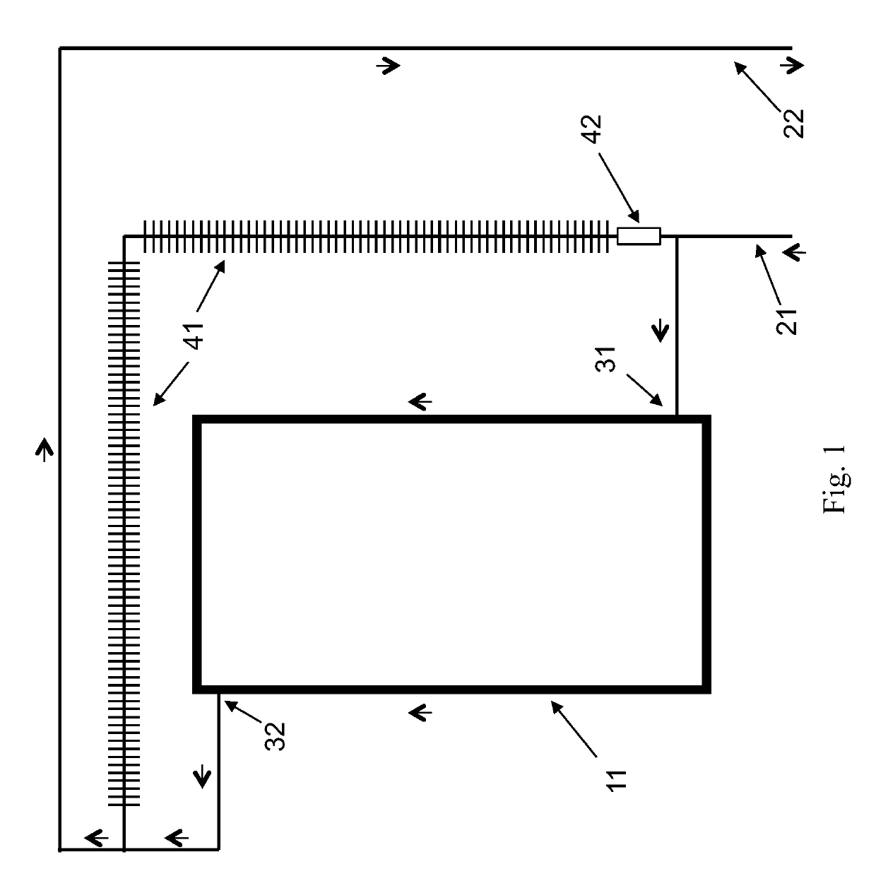
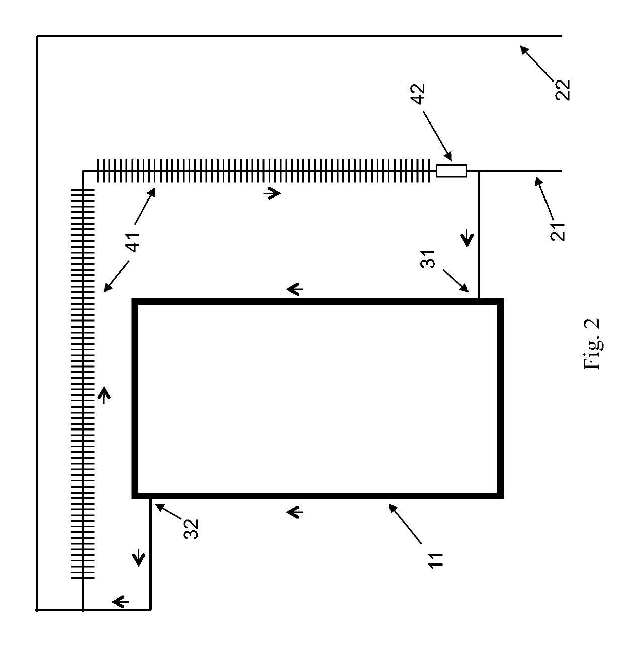
[0010]The present invention is an apparatus and corresponding method for a closed-loop fluidic system that provides overheat protection via a thermosyphon heat dump flow path that is parallel to the flow path through a solar collector and that on the cessation of forced circulation allows fluid in the solar collector to be cooled at any angle by thermosyphoning. The thermosyphon heat dump flow path is comprised of a heat dump and a fluidic diode interposed between the inlet and outlet of the solar collector. During forced circulation, the normal system operating mode, the fluidic diode prevents upward flow through the thermosyphon heat dump flow path. Flow only goes through the solar collector. When forced circulation stops, natural circulation commences to cool the solar collector with the fluidic diode now allowing downward flow through the thermosyphon heat dump flow path. The heat dump is a heat exchanger and may be liquid-to-air, liquid-to-liquid or liquid-to-solid, active or passive, powered or non-powered. Options include finned tubes, fan coils, radiators, liquid baths, shell-and-tube, plate-type, and plate-fin, among others. The invention solves the overheating problem, removes orientation restrictions on the one-way fixture for the thermosyphon heat dump flow path, and is more reliable. Embodiments of the invention can be completely passive, a great advantage when power is lost. When the design and installation include horizontal or vertical components that allow the use of either the fluidic diode or the check valve, then either may be incorporated in the thermosyphon heat dump flow path.
[0011]The object of the present invention is to improve overheat protection for solar thermal collectors experiencing a loss of forced circulation by incorporating the fluidic diode into the thermosyphon heat dump flow path. Reliability is increased because the fluidic diode has no moving parts. A greater number of solar collector designs and installations can thus be protected because the fluidic diode functions in any orientation. Another object of the present invention is to enable the manufacture of solar collectors out of much less expensive materials, such as plastic, which could be easily damaged if not protected from overheating. Note that a plastic solar collector would have to also be protected from overheating during forced circulation with another separate overheat protection device or a control system because the present invention affords overheat protection only when forced circulation stops. Another object of the present invention is to improve the appearance of thermosyphon heat dump flow path plumbing by streamlining the piping with the use of the fluidic diode and by allowing the thermosyphon heat dump flow path to be integrated into the solar collector itself.

Problems solved by technology

Some solar thermal collectors for hot water and space heating can overheat and be damaged when forced circulation stops whether by accident, design, failure or fault.
The most common situations arise when the fluidic system pump stops due to an electrical power failure or control system actions.
Non-drainback systems retain the fluid in the collector and in the hot sun can continue to heat the fluid in the collector to extremes creating the potential for damage.
Because the check valve must open by gravity or by very low thermosyphon pressure, spring-type check valves cannot be used.
However, the swing check can only operate horizontally.
These orientation requirements puts severe limits on how the thermosyphon heat dump flow paths can be designed and installed because the section of piping with the check valve is constrained to being horizontal or vertical, and solar collectors are generally installed with a slope.
In addition, the swing check and ball check valves have moving parts that can fail mechanically.
. . in the event that fluid in the solar energy absorber vaporizes, the fluid is forced out of the solar energy absorber and into the pressure vessel.” This protection system fails to prevent boiling before it starts.
The allowed boiling may damage the system or fluid in the system.
This protection system works only for flat plate solar collectors, and compromises the thermal integrity of the solar collector with openings and mechanical dampers that wear and eventually fail to close completely or properly.
This system fails to prevent boiling.
This damper system works only for flat plate solar collectors, and compromises the thermal integrity of the solar collector with openings and mechanical dampers that wear and eventually fail to close completely or properly.
This system is expensive and complex.
This application is only for boiling water reactors and cannot be directly applied to solar thermal collectors and other flowing-fluid-heating devices.

Method used


Image

  • Thermosyphon cooling for overheat protection
  • Thermosyphon cooling for overheat protection
  • Thermosyphon cooling for overheat protection

Examples


Embodiment Construction

1. Definitions

[0020]Fluidic system. “Fluidic system” is defined, herein, as a system comprising fluid, components and piping that come in contact with the fluid, and components for monitoring or controlling the system. A fluidic system may be open or closed. A fluidic system may be a subsystem of a larger fluidic system.

[0021]Piping. “Piping” is defined, herein, as a system of joined and fluid-coupled fluidic conduits through which fluid may flow from one component of a fluidic system to another. Piping includes, but is not limited to, pipes, tubes, hoses, manifolds, connectors, such as tee's or elbows, and the means for joining them to each other and to components. Piping may be rigid or flexible. Piping connections may be welded, bolted-flange, threaded, soldered, union-joint, pressure-fit, push-fit, fitting-type, compression-type, heat-welded, heat-soldered, clamped, glued, or accomplished with other joining methods.

[0022]Flow path. “Flow path” is defined, herein, as an assembly ...


PUM


Abstract

This thermosyphon cooling system cools fluid by thermosyphon to prevent overheating at a solar collector when forced circulation stops. The introduction of the fluidic diode in the thermosyphon heat dump flow path affords more design and installation options, higher reliability, and the opportunity to manufacture solar collectors of less expensive alternative materials.

Description

BACKGROUND OF THE INVENTION1. Field of the Invention[0001]The present invention relates to fluidic systems in which a solar thermal collector or similar flowing-fluid-heating device may experience a loss of forced circulation and require cooling to prevent damage.2. Description of the Prior Art[0002]Some solar thermal collectors for hot water and space heating can overheat and be damaged when forced circulation stops whether by accident, design, failure or fault. The most common situations arise when the fluidic system pump stops due to an electrical power failure or control system actions. Drainback solar thermal systems avoid overheating damage by allowing the fluid to drain out of the collectors. Non-drainback systems retain the fluid in the collector and in the hot sun can continue to heat the fluid in the collector to extremes creating the potential for damage.[0003]One of the ways of arresting this heat up for non-drainback systems is to provide a heat dump flow path that beco...

Claims


Application Information

Patent Timeline
Patent Type & Authority Patents(United States)
IPC IPC(8): F24S90/10F24S90/00F24S40/55F24S10/90F24S10/50F24S10/30F24S10/40
CPCF24S90/10F24S10/90F24S40/55F24S90/00F24S10/50F24S10/30F24S10/40Y02E10/44
Inventor WEHNER, THOMAS RICHARD
Owner WEHNER THOMAS RICHARD
Why Eureka
Try Eureka