Hopper-loading method and installation

a technology of hopper and hopper body, which is applied in the direction of charging manipulation, lighting and heating apparatus, furnaces, etc., can solve the problems of difficult to distribute charge materials uniformly in the hopper, affecting the uniformity of the distribution of materials, so as to achieve the effect of better distribution of materials in the hopper

Inactive Publication Date: 2009-10-20
PAUL WURTH SA
View PDF7 Cites 8 Cited by
  • Summary
  • Abstract
  • Description
  • Claims
  • Application Information

AI Technical Summary

Benefits of technology

[0012]By subdividing the curtain of material transversely to its lateral extent into several partial streams, it is possible to make sure that the large and fine particle composition of the partial streams is essentially the same. Indeed, if the distribution of material varies greatly from the front of the curtain of material to the rear, viewed in the direction in which the loose material is conveyed, it is, on the other hand, essentially constant in the direction of the lateral extent of the curtain, that is to say, from left to right. It then follows that dividing the curtain and deflecting the partial streams toward distinct regions of the hopper makes sure that these different regions are loaded with material of comparable composition. This on the whole guarantees a better distribution of material, even though within the partial streams, the segregation phenomenon remains. By varying the position of the laterally moveable deflector, it becomes possible to vary the partial flow width and therefore the amount of material contained in these partial streams.
[0013]In a preferred embodiment, the method further comprises the step of regulating the flow rates of material in the partial streams by adjusting the points at which said curtain of material is split. Due to the mechanisms associated with conveying material in loose form, either on a conveyor belt or using skip elevators, the curtain of material is generally thicker in the middle of the curtain than at the outer regions. As a result, the material content of the curtain is higher at the middle of the curtain than on its outside. By choosing the points at which the curtain is split with care, this difference in material content can easily be compensated for. If, for example, the curtain is split into four adjacent partial streams, then the curtain will be subdivided in such a way that the central partial streams are narrower than the outer streams.
[0017]It should be noted that the fact of splitting the curtain of material transversely to its lateral extent ensures essentially equal composition in the partial streams even if the tipping-out point is offset from the central axis of the hopper.
[0019]Said wall or walls preferably extend up to the height of the top opening of the said box. Thus, the curtain is effectively split as soon as it enters the box. This ensures a constant ratio between the amounts of material tipped out into the different regions of the hopper, even if the rate of tipping out differs from one tipping-out means to another.

Problems solved by technology

However, it is difficult to distribute the charge materials uniformly in the hopper because of the particle size of the charge material.
The problem is that the charge material, whether it be iron ore particles or coke particles, has a varying and non-uniform particle size.
This distribution of the particles in the curtain of material has the effect that, after loading, the rear part of the hopper, viewed in the direction in which the material is conveyed, contains more large particles than the front part and that the distribution of material is therefore distinctly non-uniform.
Unfortunately, the segregation of the material due to the pouring cone within the hopper cannot be reduced.
Such a rotary hopper cannot therefore meet the requirements of uniform charging of a shaft furnace.
Given the size and weight of such a hopper, this step entails a considerable investment and poses problems in terms of installation maintenance.

Method used


Image

  • Hopper-loading method and installation
  • Hopper-loading method and installation
  • Hopper-loading method and installation

Examples


Embodiment Construction

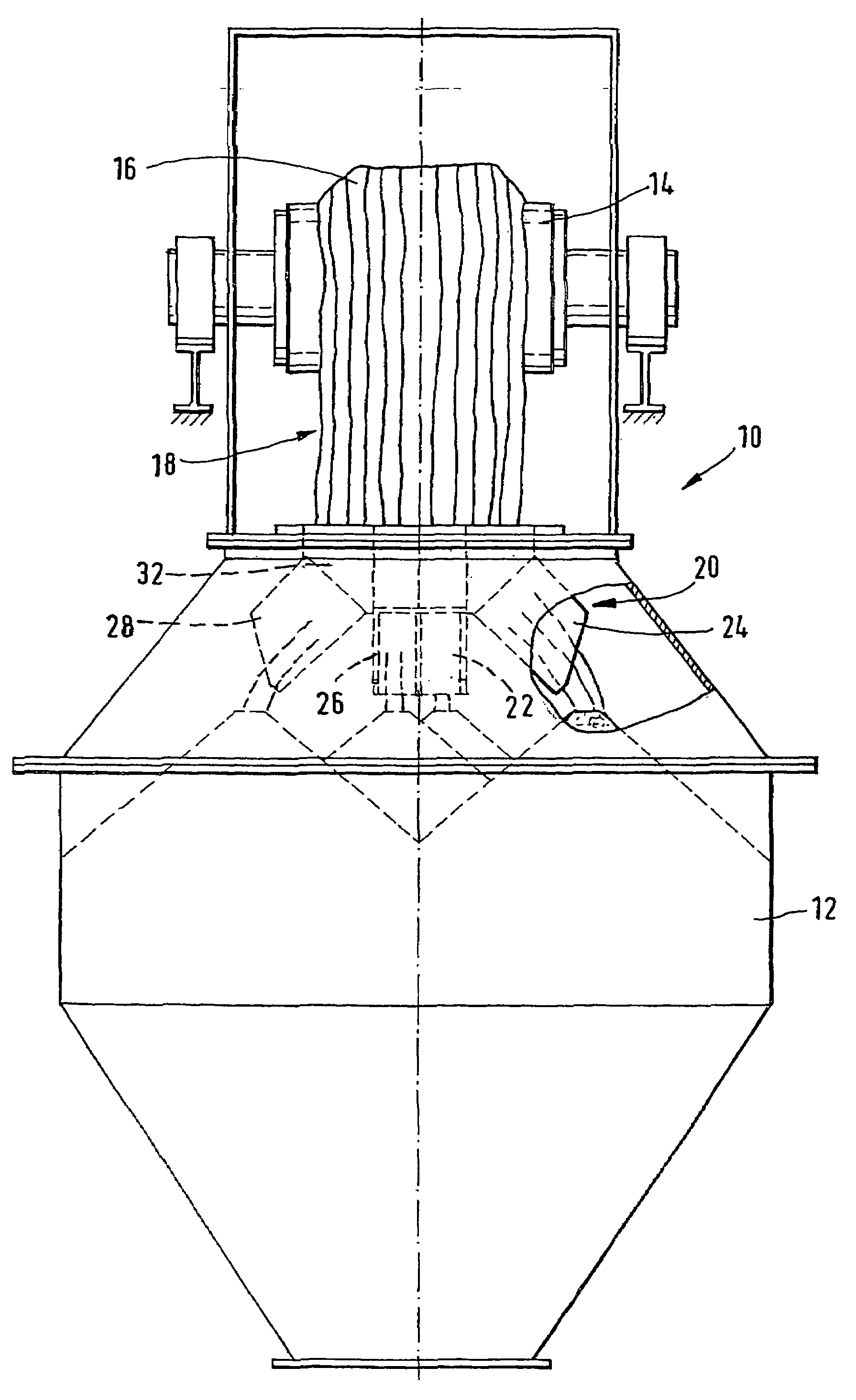
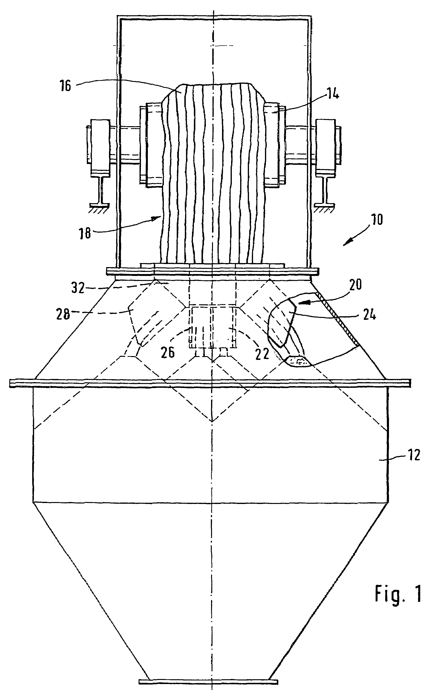
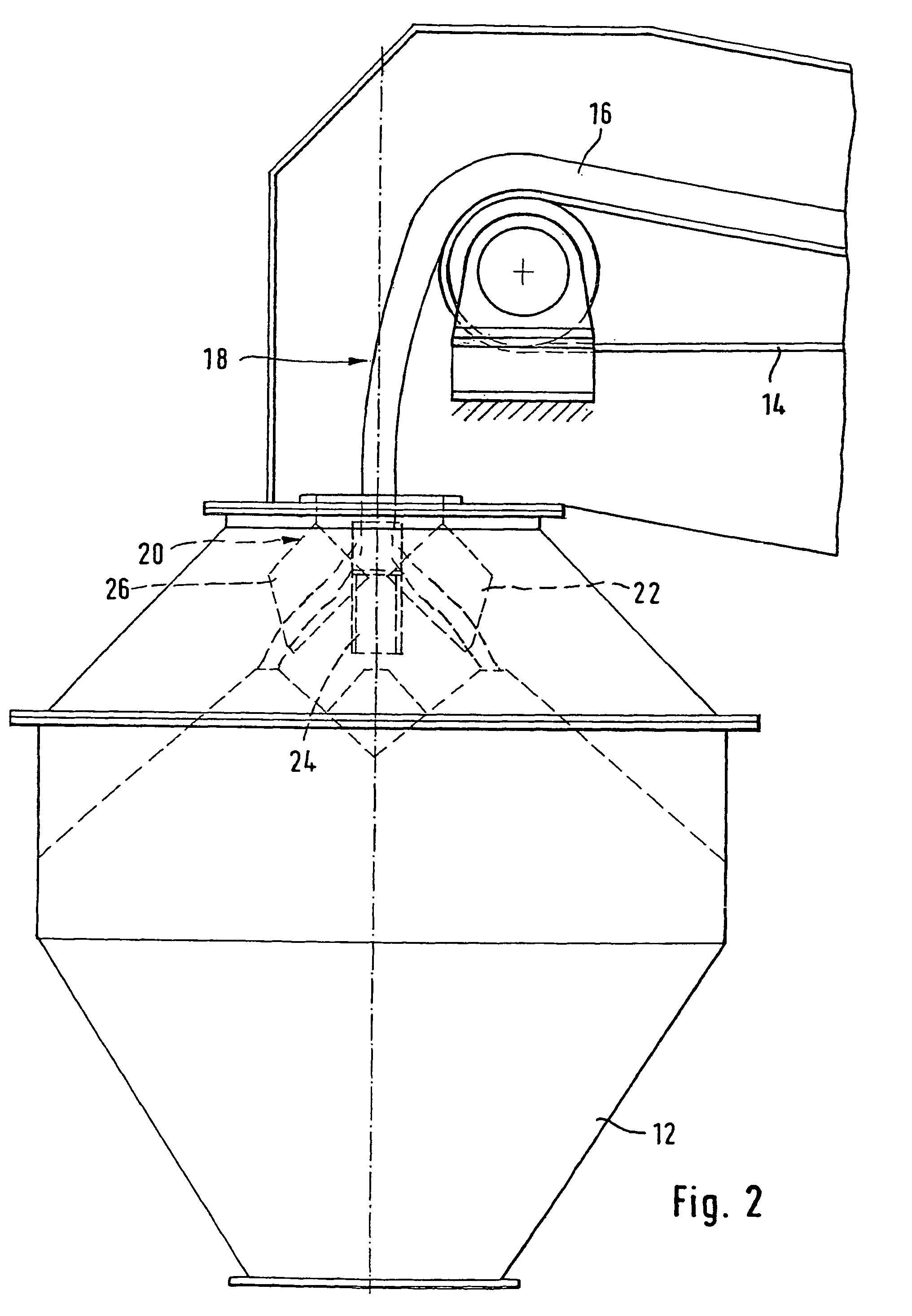
[0033]FIGS. 1 and 2 respectively show a front view and a side view of an installation 10 for loading a hopper 12. The installation 10 comprises a conveyor belt 14 which conveys the loose material 16 over the hopper 12. The loose material is tipped out more or less over the central axis of the hopper 12 and therefore falls in the form of a curtain of material 18 into the top opening of the hopper 12.

[0034]To ensure good distribution of the loose material within the hopper, a device 20 for distributing loose material is arranged in the top opening of the hopper 12.

[0035]The device 20 comprises several chutes 22, 24, 26, 28, which are oriented in distinct directions so as to tip the loose material out into different regions of the hopper. The different chutes are mounted side by side in a top frame 30, so as to form a box 32 which is open at the top and divided into several adjacent compartments by walls 34 of the chutes. The chutes are produced in such a way that the walls delimiting ...


PUM

PropertyMeasurementUnit
flow ratesaaaaaaaaaa
heightaaaaaaaaaa
particle sizeaaaaaaaaaa

Abstract

A device for distributing loose materials, arranged in a curtain of loose material tipped out from a means of conveying loose material includes a box with a top opening, at least one wall which extends transverse to the curtain of material inside the box to subdivide the box into at least two compartments, and at least two tipping-out means, one of the tipping-out means being associated with each of the compartments of the box, the tipping-out means being directed in such a way as to deflect the material received in the respective compartments into a distinct region of the hopper. The method for loading a hopper includes tipping loose material out in the form of a curtain of material over the hopper and splitting the curtain into at least two partial streams so as to deflect each of the partial streams towards a distinct region of the hopper.

Description

CROSS-REFERENCE TO RELATED APPLICATIONS[0001]This application is entitled to the benefit of International Application No. PCT / EP04 / 00421 filed on Jan. 20, 2004, and Luxembourg Patent Application No. 91 000 filed on Jan. 21, 2003.FIELD OF THE INVENTION[0002]The present invention relates to a hopper loading installation, particularly in a shaft furnace loading installation.BACKGROUND OF THE INVENTION[0003]To guarantee optimum charging of a shaft furnace, it is desirable for the materials stored in the storage hopper to be distributed fairly uniformly. However, it is difficult to distribute the charge materials uniformly in the hopper because of the particle size of the charge material. The problem is that the charge material, whether it be iron ore particles or coke particles, has a varying and non-uniform particle size. As the material is conveyed towards the hopper, for example via a conveyor belt, the fine particles have a tendency to build up in larger proportions at the bottom of...

Claims


Application Information

Patent Timeline
Patent Type & Authority Patents(United States)
IPC IPC(8): B65G65/00B65G65/30B65G69/04C21B7/20F27D3/00F27D3/10F27D3/12
CPCB65G69/0441C21B7/20F27D3/10F27D3/0033F27D3/12F27B1/20B65G11/20
Inventor CIMENTI, GIOVANNILONARDI, EMILETHILLEN, GUY
Owner PAUL WURTH SA
Why Eureka
Try Eureka