Multimode amplifier for operation in linear and saturated modes

a multi-mode amplifier and linear mode technology, applied in the field of amplifier circuits, can solve problems such as slew rate limits on mode transitions, increase in component counts, and compromise of noise performan

Active Publication Date: 2009-10-20
SKYWORKS SOLUTIONS INC
View PDF10 Cites 72 Cited by
  • Summary
  • Abstract
  • Description
  • Claims
  • Application Information

AI Technical Summary

Problems solved by technology

However, the switched bias technique utilized in this approach can require a complex circuit to switch the bias between operating modes, which can undesirably result in an increased component count, compromised noise performance, and slew rate limits on mode transitions.
While this approach avoids switching the bias between linear and saturated operating modes, it requires a high current low drop out regulator (LDO) to support the current requirements of the output stage amplifier and introduces an undesirable voltage drop in the supply voltage of the amplifier, thereby reducing overall amplifier efficiency and the linear operating mode performance.

Method used


Image

  • Multimode amplifier for operation in linear and saturated modes
  • Multimode amplifier for operation in linear and saturated modes
  • Multimode amplifier for operation in linear and saturated modes

Examples


Embodiment Construction

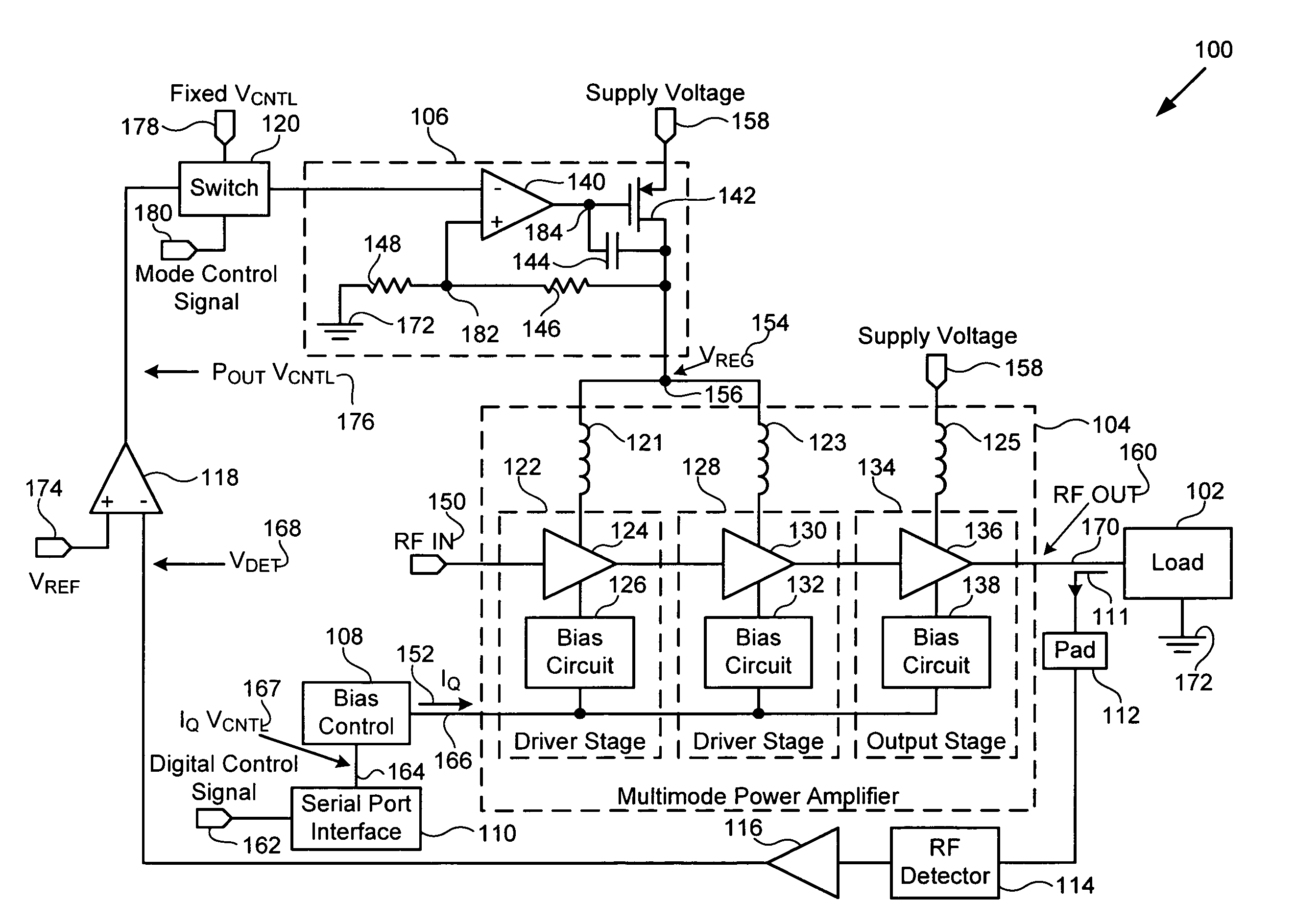
[0013]The present invention is directed to a multimode amplifier for operation in linear and saturated modes. The following description contains specific information pertaining to the implementation of the present invention. One skilled in the art will recognize that the present invention may be implemented in a manner different from that specifically discussed in the present application. Moreover, some of the specific details of the invention are not discussed in order not to obscure the invention. The specific details not described in the present application are within the knowledge of a person of ordinary skill in the art.

[0014]The drawings in the present application and their accompanying detailed description are directed to merely exemplary embodiments of the invention. To maintain brevity, other embodiments of the invention which use the principles of the present invention are not specifically described in the present application and are not specifically illustrated by the pre...


PUM


Abstract

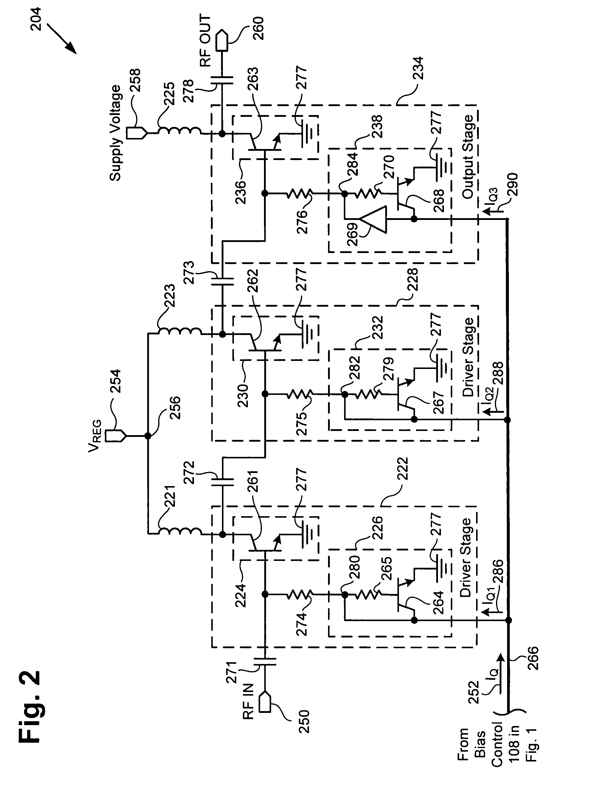
According to an exemplary embodiment, a multimode power amplifier configured to receive an RF input signal and provide an RF output signal in linear and saturated operating modes includes an output stage configured to receive a fixed supply voltage and to provide the RF output signal. The multimode power amplifier further includes at least one driver stage coupled to the output stage, where the at least one driver stage is configured to receive the RF input signal and an adjustable supply voltage. The adjustable supply voltage controls an RF output power of the RF output signal when the multimode power amplifier is in the saturated operating mode. The at least one driver and the output stage are each biased by a low impedance voltage in the linear and saturated operating modes. The adjustable supply voltage can be controlled by a fixed control voltage in the linear operating mode.

Description

[0001]The present application claims the benefit of and priority to a pending provisional patent application entitled “Biasing Architecture for a Multimode Power Amplifier,” Ser. No. 60 / 897,711 filed on Jan. 25, 2007. The disclosure in that pending provisional application is hereby incorporated fully by reference into the present application.BACKGROUND OF THE INVENTION[0002]1. Field of the Invention[0003]The present invention generally relates to the field of electrical circuits. More particularly, the invention relates to amplifier circuits.[0004]2. Background Art[0005]Communication devices, such as cellular telephones, generally utilize power amplifiers that operate in a linear mode, where output power is controlled by input power, and power amplifiers that operate in a saturated mode, where input power is constant and output power is controlled by a control voltage, to support different modulation standards. For example, power amplifiers that can operate in a linear mode can be u...

Claims


Application Information

Patent Timeline
Patent Type & Authority Patents(United States)
IPC IPC(8): H03G3/20
CPCH03F3/19H03F1/0233H03F3/20
Inventor RIPLEY, DAVID S.REGINELLA, PAT
Owner SKYWORKS SOLUTIONS INC
Why Eureka
Try Eureka