Golf club head

a golf club and head technology, applied in golf clubs, sport equipment, golf, etc., can solve problems such as shocks and vibrations, and achieve the effects of improving the durability of the head, improving the joint strength of the face member, and good impact feeling for users

Active Publication Date: 2009-10-27
SUMITOMO RUBBER IND LTD
View PDF28 Cites 38 Cited by
  • Summary
  • Abstract
  • Description
  • Claims
  • Application Information

AI Technical Summary

Benefits of technology

[0004]It is therefore an object of the present invention to provide a hybrid golf club head in which the concentration of the shocks and vibrations occurring when the ball is hit are avoided, and the strength of the junction is increased, thereby the durability of the head is improved.
[0006]Therefore, the contact area or bonded area of the two parts: the face member and main body is increased, and the formation of such a junction at which the club head material changes from a metal to a FRP or vice versa can be avoided. Therefore, the durability of the head is improved and the joint strength of the face member can be increased. Further, the vibrations of the metal face member at impact can be damped by the fiber-reinforced plastic of the front portion lining the face member, and as a result it is possible to present a good impact feeling for the user.

Problems solved by technology

But, when the ball is hit on the metal face plate, the shocks and vibrations thereof concentrate in the junction at the perimeter of the face plate.

Method used


Image

  • Golf club head
  • Golf club head
  • Golf club head

Examples


working example 1 to 8

[0058]The main body was made from prepreg of an epoxy resin (“350 plastic” Mitsubishi Rayon Co., Ltd.) and carbon fibers having a tensile elastic modulus of 240.3 GPa (“TR50S” Mitsubishi Rayon Co., Ltd.) by the pressure bag molding method as explained above in conjunction with FIGS. 8 and 9. The prepreg sheets were applied to the bag so as to form a five-layered structure. The hole 13 was patched with a plastic badge. The face member was made of Ti-5.5Al-1Fe (“super TI-X 51AF” Nippon steel corporation). The face member was bonded to the main body by placing the face member in the mold.

working examples 1 to 7

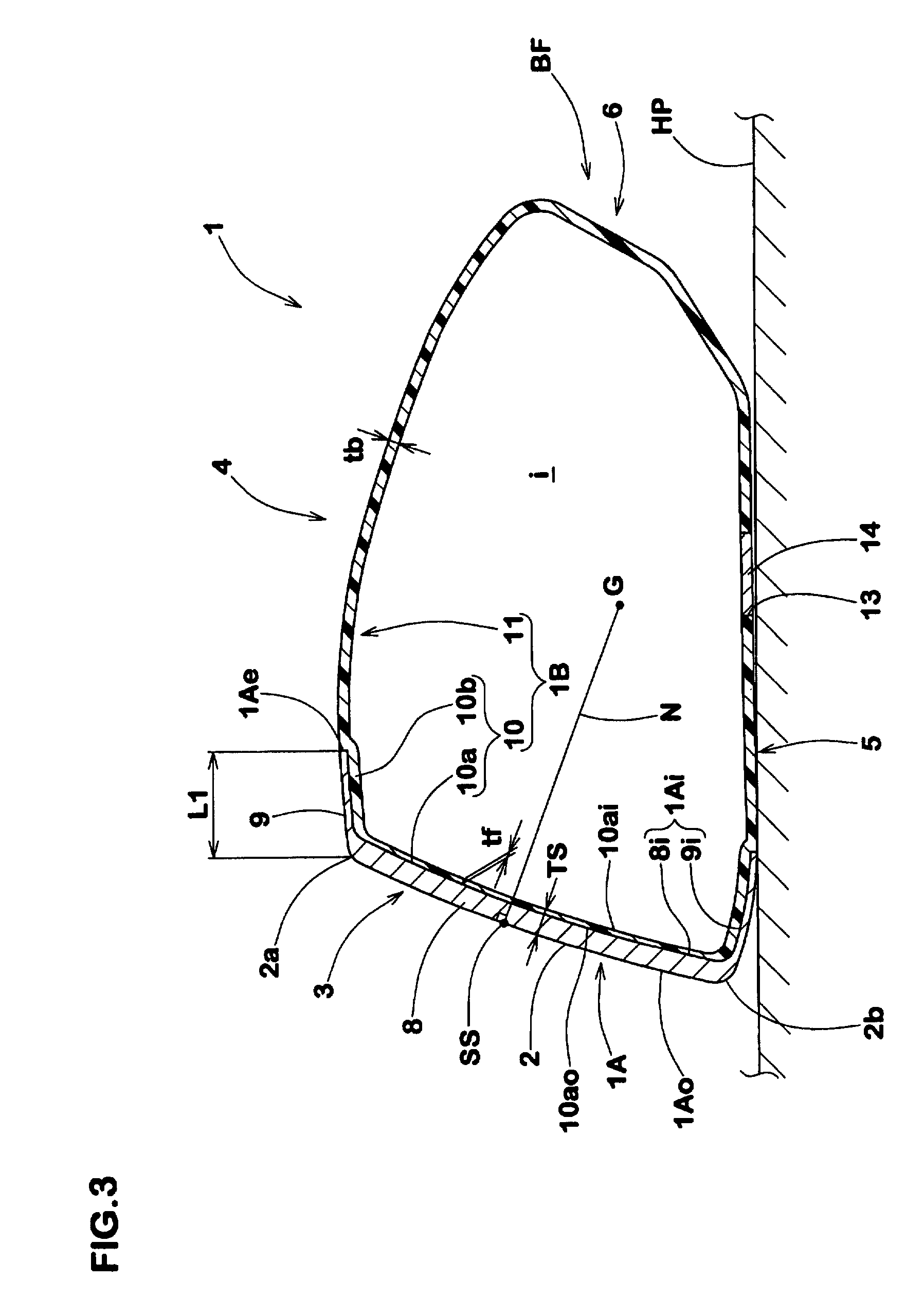
[0059]The face member was formed by forging and made up of the face plate and turnback as shown in FIGS. 3 and 4.

working example 1

[0060]The face plate had a constant thickness.


PUM


Abstract

A hollow golf club head comprises: a hollow main body made of a fiber-reinforced plastic; and a face member made of a metal material and forming at least a part of the club face, wherein the hollow main body is single-piece and comprises a front portion of which outer surface is covered with the face member bonded thereto.

Description

BACKGROUND OF THE INVENTION[0001]The present invention relates to a hybrid golf club head of a metal part and an FRP part[0002]Wood-type hollow golf club heads composed of an open-front main body made of a fiber-reinforced plastic and a metal face plate of which outside perimeter is fixed to the main body so as to close the front opening of the main body have been proposed for example as disclosed in US patent application publication US 2003 / 207726 A1.[0003]In such a structure, as the fiber-reinforced plastics are generally smaller in the specific gravity than the metal materials, the design freedom of the weight distribution of the head is increased. Therefore, the design freedom of the position of the center of gravity of the head is also increased, and it is possible to adjust the center of gravity to a low position as desired. But, when the ball is hit on the metal face plate, the shocks and vibrations thereof concentrate in the junction at the perimeter of the face plate. There...

Claims


Application Information

Patent Timeline
Patent Type & Authority Patents(United States)
IPC IPC(8): A63B53/04A63B102/32
CPCA63B53/0466A63B2053/0408A63B2053/0416A63B53/047A63B2053/0458A63B2209/02A63B2209/023A63B53/0408A63B53/0416A63B53/0458
Inventor NISHIO, MASAYOSHI
Owner SUMITOMO RUBBER IND LTD
Why Eureka
Try Eureka