Device to aid in placing tracheal tubes

a tracheal tube and tube tube technology, applied in the field of tracheal tube intubation devices, can solve the problems of difficult glottic aperture visualization by secretions, poor visualization once of glottic aperture, and no device, however, provides dedicated means for allowing for aspiration of secretions or improving visualization, so as to achieve the effect of convenient insertion

Active Publication Date: 2009-10-27
CITY OF HOPE
View PDF35 Cites 53 Cited by
  • Summary
  • Abstract
  • Description
  • Claims
  • Application Information

AI Technical Summary

Benefits of technology

[0017]In addition to the benefits of single-handed laryngeal suspension, secretion aspiration, oxygenation, and direct visualization, the apparatus of the present invention allows a fibre-optic cable to be easily inserted into the trachea, which can be connected to a video device for purposes of indirect visualization. Such indirect visualization is useful for documentation, instruction, or to assist in tracheal intubation.

Problems solved by technology

Often times the glottic aperture is rendered difficult to visualize by secretions (i.e., blood, mucus, gastric contents, foreign debris, etc.).
Many times these secretions continue to build up after the operator has cleared them initially, thereby rendering the glottis poorly visualized once again.
None of these devices, however, provide dedicated means to allow for aspiration of secretions or for improved visualization, while simultaneously allowing for single-handed insertion of endotracheal tubes.

Method used


Image

  • Device to aid in placing tracheal tubes
  • Device to aid in placing tracheal tubes
  • Device to aid in placing tracheal tubes

Examples


Embodiment Construction

[0032]An exemplary embodiment of a device to aid in placing tracheal tubes according to the present invention is described herein.

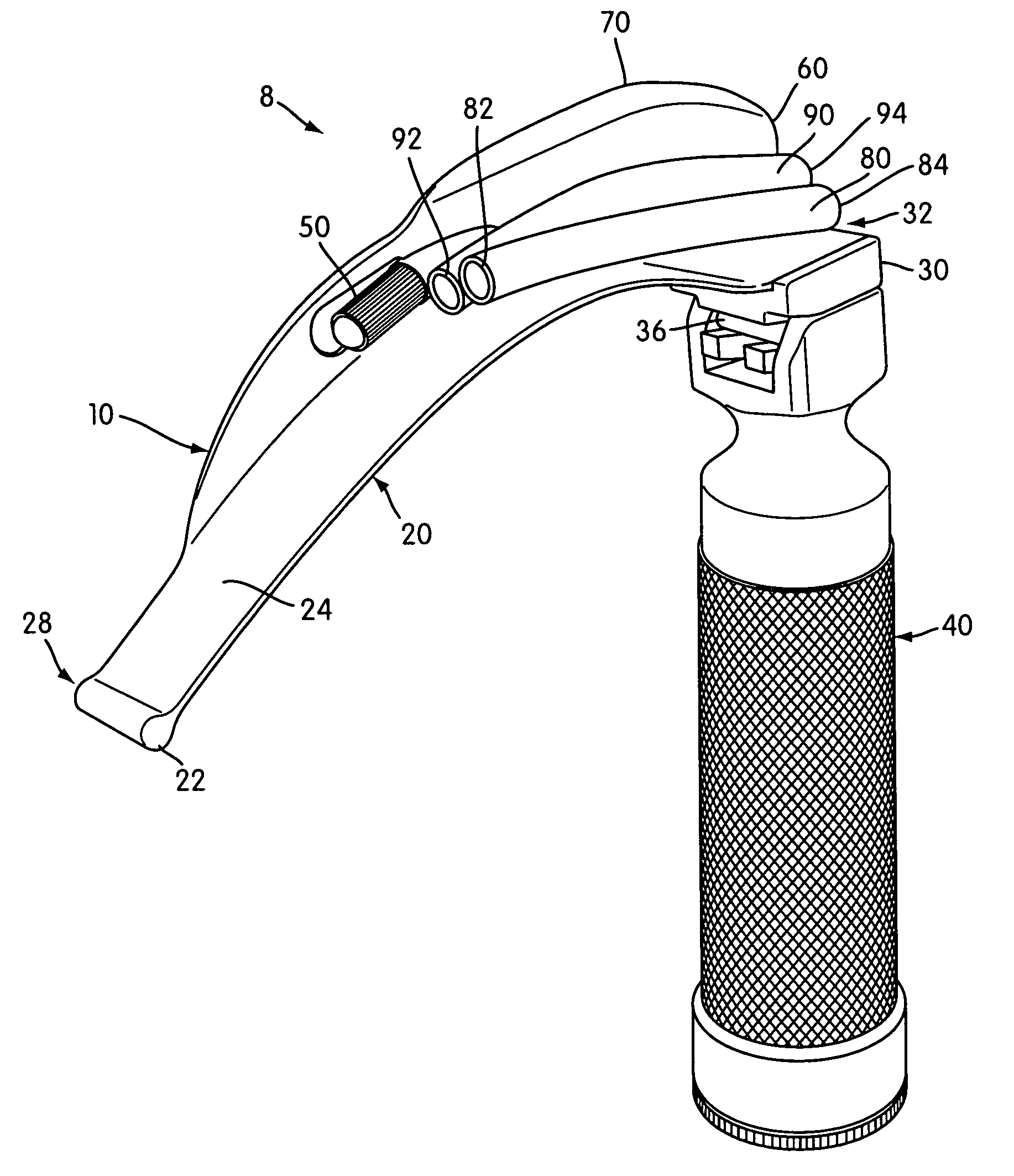
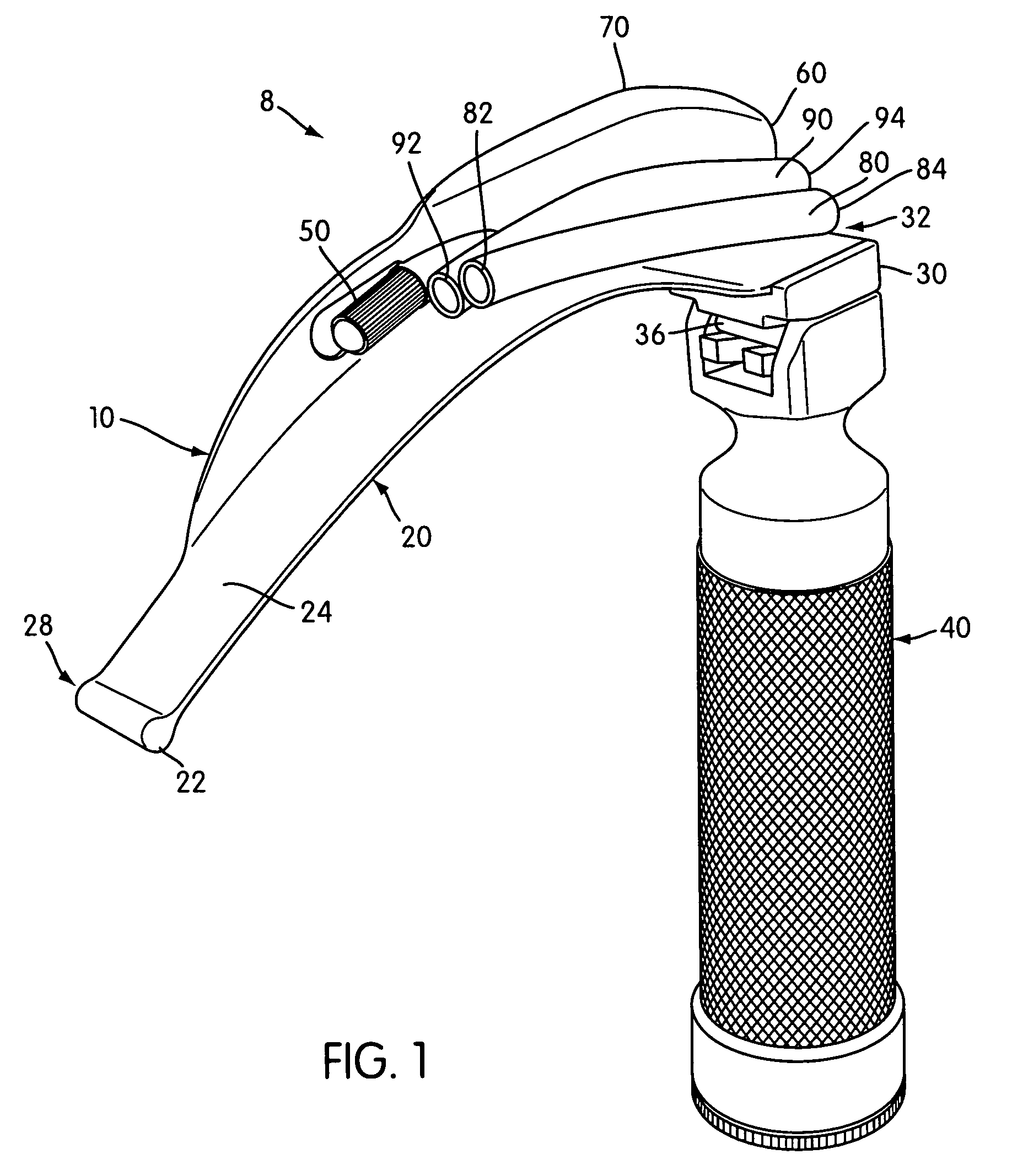
[0033]Referring now in detail to the drawings there is in FIG. 1 a laryngoscope 8 including the blade assembly 10 according to one aspect of the present invention attached in a conventional manner to a handle 40. The blade assembly 10 comprises an elongated, curved blade 20, a base 30 for coupling blade assembly 10 to handle 40, a light source 50, a tongue deflector 60, a horizontal flange 70 attached to tongue deflector 60, a first guide tube 80, and a second guide tube 90.

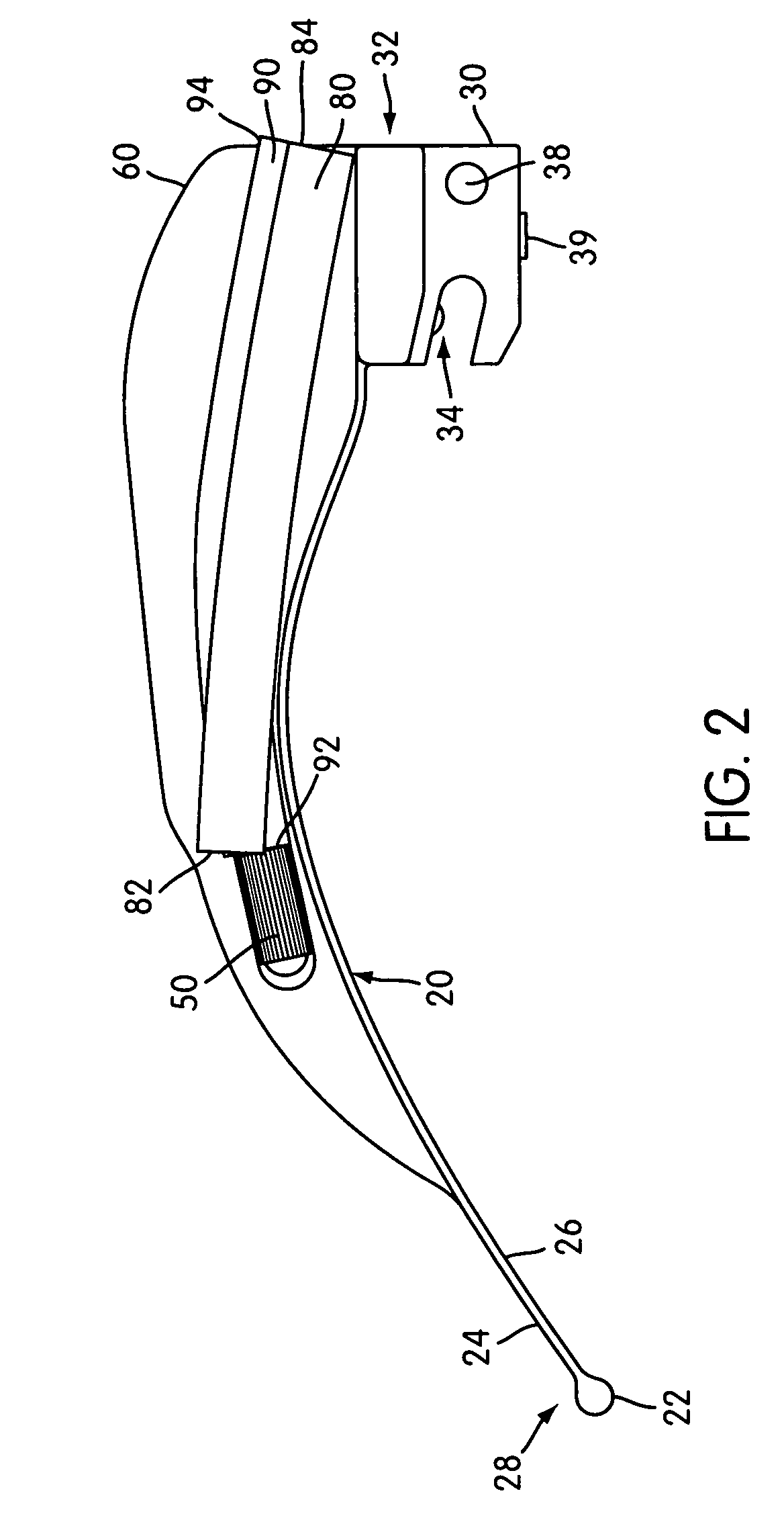
[0034]Viewing the curved blade 20 in more detail, there is in FIGS. 2-4 a proximal end 32, a distal end 28, an upper surface 24, and a lower surface 26. The distal end 28 incorporates a bulbous tip 22 projecting outward from the proximal end, which minimizes the risk of damage to tissues within the oral cavity when the laryngoscope is inserted into the patient's mouth. The curved blade...


PUM


Abstract

A laryngoscope includes a blade assembly with a base that is coupled to a handle. Attached to the blade assembly are two hollow guide tubes that generally follow along the longitudinal axis of the blade assembly. The two tubes are oriented at different angles of attack for directing aspirating and / or oxygenating tubes into different regions of the patient's oral cavity. The handle has an ergonomic shape to conform to the user's hand, thereby facilitating the user's application of a downward force necessary to effect laryngeal suspension. A tube extension / retraction mechanism effects user-controlled powered movement of an aspiration / oxygenation tube into or out of the patient's oral cavity. A bayonette connection is provided for connecting the blade assembly to the handle.

Description

[0001]This application claims the benefit of U.S. Provisional Patent Application No. 60 / 448,881, filed on Feb. 24, 2003, the contents of which are incorporated herein by this reference.BACKGROUND OF THE INVENTION[0002]1. Field of the Invention[0003]The present invention relates generally to tracheal intubation devices and, in particular, to a tracheal intubation device that allows single handed laryngeal suspension, secretion aspiration, oxygenation, and visualization.[0004]2. Background and Related Art[0005]Laryngoscopes are generally used during tracheal intubation procedures, both in surgical situations and in any emergency situation requiring access to a patient's mouth and throat. Laryngoscopes are used to suspend the oral cavity, Pharynx and associated structures open for insertion of, for example, endotracheal tubes, which may facilitate positive pressure ventilation for the patient's lungs.[0006]Generally, a laryngoscope comprises a handle and a blade portion. Laryngoscopes ...

Claims


Application Information

Patent Timeline
Patent Type & Authority Patents(United States)
IPC IPC(8): A61B1/267
CPCA61B1/267A61B1/06A61B1/012
Inventor DUNST, MORDECAI
Owner CITY OF HOPE
Why Eureka
Try Eureka