Flight control surface actuator assembly including a free trial mechanism

a technology of actuators and free trials, applied in the direction of gearing, slip couplings, hoisting equipments, etc., can solve the problems of actuators that are used to be subject to relatively severe environmental conditions, relatively high magnitude shock and vibration, actuators could become jammed or otherwise inoperable,

Active Publication Date: 2009-11-03
HONEYWELL INT INC
View PDF33 Cites 31 Cited by
  • Summary
  • Abstract
  • Description
  • Claims
  • Application Information

AI Technical Summary

Problems solved by technology

In many applications such as, for example, aircraft flight surface control systems and thrust reverser actuation control systems, the actuators that are used may be subject to relatively severe environmental conditions, as well as relatively high magnitude shock and vibration.
As a result of, for example, the environmental conditions, and relatively high magnitude shock and vibration an actuator experiences, the actuators could become jammed or otherwise inoperable.
For example, the actuator gear train could potentially jam or, if the actuator is a ballscrew-type actuator, the ball returns could become jammed.
Under such conditions the actuator may “lock up” or otherwise become inoperable.
Though such situations are unlikely, analysis has shown that secondary damage to other portions of the actuator, or to various portions of the system in which the actuator is installed, may result under certain postulated circumstances.
This postulated condition may result in damage to the actuator or the system in which it is installed.
Repairing such damage can be costly and result in system down time.
One solution is to use stronger components, but this increases the cost and / or weight of the system.
However, this solution may also increase system cost and / or weight.

Method used


Image

  • Flight control surface actuator assembly including a free trial mechanism
  • Flight control surface actuator assembly including a free trial mechanism
  • Flight control surface actuator assembly including a free trial mechanism

Examples


Embodiment Construction

[0013]The following detailed description of the invention is merely exemplary in nature and is not intended to limit the invention or the application and uses of the invention. Furthermore, there is no intention to be bound by any theory presented in the preceding background of the invention or the following detailed description of the invention.

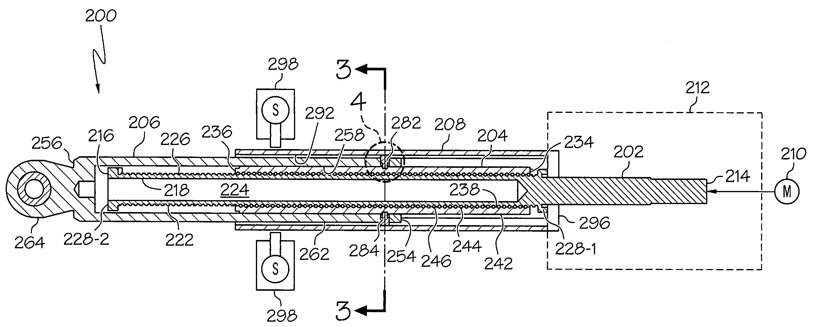
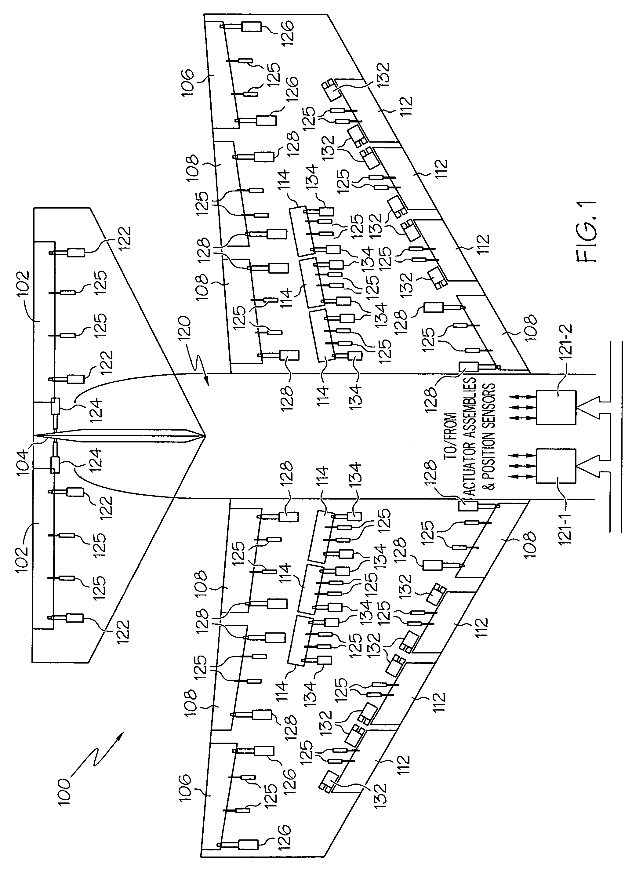
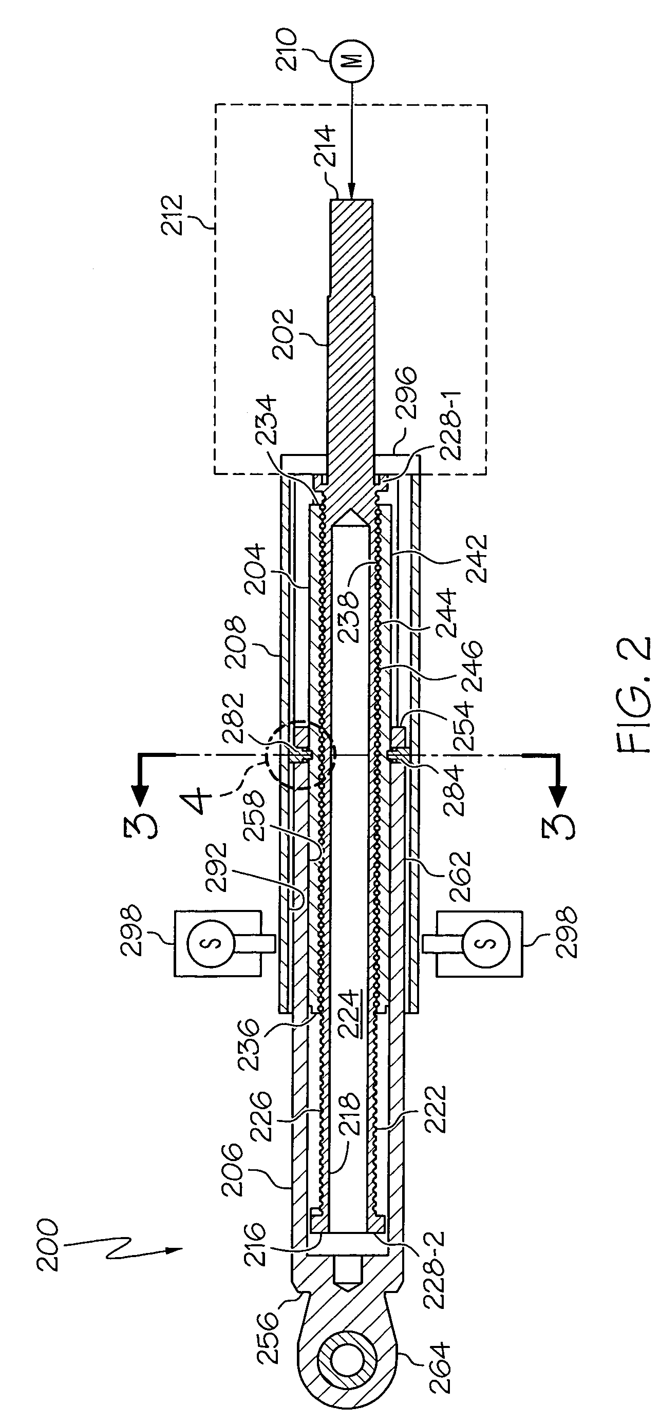
[0014]Turning first to FIG. 1, a schematic diagram of a portion of an exemplary aircraft and a portion of an exemplary flight control surface actuation system is shown. In the illustrated embodiment, the aircraft 100 includes a pair of elevators 102, a rudder 104, and a pair of ailerons 106, which are the primary flight control surfaces, and a plurality of flaps 108, slats 112, and spoilers 114, which are the secondary flight control surfaces. The primary flight control surfaces 102-106 control aircraft movements about the aircraft pitch, yaw, and roll axes. Specifically, the elevators 102 are used to control aircraft movement about the pitc...


PUM


Abstract

A flight control surface actuator includes a mechanism that enables the actuator translation member to be selectively decoupled from the actuator rotating member. The actuator includes an actuation member, a translation member, an extension member, and a locking member. The actuation member is adapted to receive a drive force and is configured, in response to the drive force, to rotate and cause the translation member to translate. The extension member surrounds at least a portion of the translation member and is configured to be selectively coupled to, and decoupled from, the translation member. The locking member surrounds at least a portion of the extension tube and is movable between a lock position, in which the locking member couples the extension member to the translation member, and a release position, in which the locking member decouples the extension member from the translation member.

Description

CROSS-REFERENCES TO RELATED APPLICATIONS[0001]This application claims the benefit of U.S. Provisional Application No. 60 / 737,245, filed Nov. 15, 2005.TECHNICAL FIELD[0002]The present invention relates to actuators and, more particularly, to a flight control surface actuator that includes a mechanism that enables the actuator translation member to be selectively decoupled from the actuator rotating member.BACKGROUND[0003]Actuators are used in myriad devices and systems. For example, many vehicles including, for example, aircraft, spacecraft, watercraft, and numerous other terrestrial and non-terrestrial vehicles, include one or more actuators to effect the movement of various control surfaces or components. In many applications such as, for example, aircraft flight surface control systems and thrust reverser actuation control systems, the actuators that are used may be subject to relatively severe environmental conditions, as well as relatively high magnitude shock and vibration.[000...

Claims


Application Information

Patent Timeline
Patent Type & Authority Patents(United States)
IPC IPC(8): F16H1/24
CPCB64C13/28B64C13/503F16H25/20Y10T74/19735F16H25/2204B64C13/505B64C13/341
Inventor WINGETT, PAUL T.HANLON, CASEYPOTTER, CALVIN C.
Owner HONEYWELL INT INC
Why Eureka
Try Eureka