Pneumatic vehicle stabilization system

a technology of pneumatic vehicle and stabilization system, which is applied in the direction of transportation items, pedestrian/occupant safety arrangements, tractors, etc., to achieve the effect of optimizing stability and best possible stability

Active Publication Date: 2009-11-03
INT TRUCK INTPROP LLC
View PDF30 Cites 48 Cited by
  • Summary
  • Abstract
  • Description
  • Claims
  • Application Information

AI Technical Summary

Problems solved by technology

Response to this input may be limited by inputs from the extension measurement sensors but level control does not operate to make spring extension equal unless the vehicle is on level ground.

Method used


Image

  • Pneumatic vehicle stabilization system
  • Pneumatic vehicle stabilization system
  • Pneumatic vehicle stabilization system

Examples


Embodiment Construction

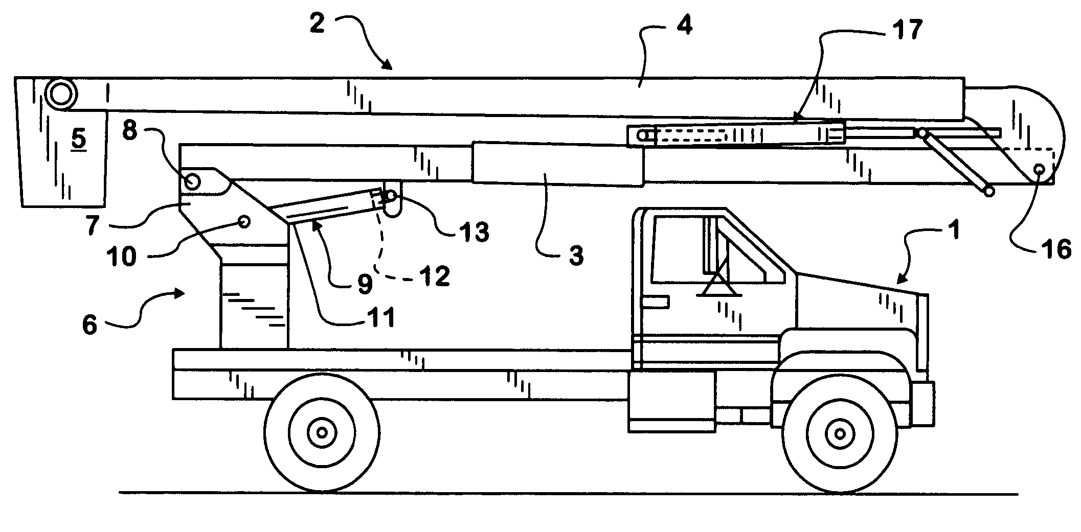
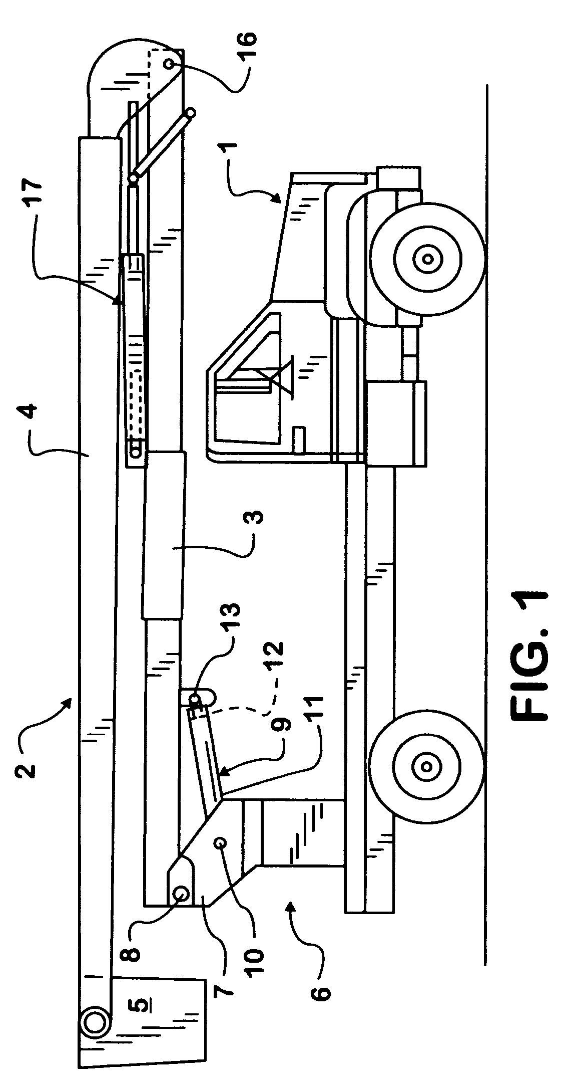
[0013]Referring to the drawings, and particularly to FIG. 1, an example of a mobile aerial lift unit is illustrated in simplified presentation for clarity of illustration. The mobile aerial lift apparatus includes a truck 1 with an aerial lift unit 2 mounted to the bed thereof. The aerial lift unit 2 includes a lower boom 3 and an upper boom 4 pivotally interconnected to each other and to the truck bed through support 6 and rotatable support bracket 7. A basket 5 is shown secured to the outer end of the upper boom 4 within which the operating personnel are located during the lifting to and locating within a selected work area in accordance with known practice. Basket 5 is typically pivotally attached to the out end of the boom 4 to maintain a horizontal (level) orientation at all times. The aerial lift unit is mounted to the truck bed through support 6. A rotatable support bracket 7 is secured to the support 6 and projects upwardly. The lower boom 3 is pivotally connected as at pivo...


PUM


Abstract

An electronic height control system for a vehicle chassis air suspension is modified to provide bimodal operation. In the second mode of operation the chassis air suspension system is maintain a stationary in a stable, level position to serve as a base for a mobile aerial lift unit installed on the vehicle. Operation of the suspension system in its stabilization and leveling mode is triggered by activation of a vehicle power take-off unit (“PTO”) used to position the aerial lift unit.

Description

BACKGROUND OF THE INVENTION[0001]1. Technical Field[0002]The invention relates to motor vehicle suspension systems and more particularly to a suspension system for motor vehicles which carry and support positionable loads such as aerial lift units.[0003]2. Description of the Problem[0004]Aerial lift units, used for accessing equipment mounted on utility poles or for tree trimming, are conventionally mounted on medium duty trucks. The truck provides a base for the aerial lift unit, and is subjected to differing rotational moments as the aerial lift unit is extended and positioned. Off center loads on the vehicle suspension obviously tend to cause the vehicle to tip to one side or to lean forward or backwards. To stabilize vehicles either outriggers have been used or the vehicles have been equipped with torsion bars. Outriggers are in effect struts which extend outwardly from the vehicle into contact with the ground to stabilize the vehicle. Outriggers though require side to side clea...

Claims


Application Information

Patent Timeline
Patent Type & Authority Patents(United States)
IPC IPC(8): B60K25/00B60G11/26B60G17/00
CPCB60G17/0195B60G2800/85B60G2800/20
Inventor DELANEY, PATRICK M.
Owner INT TRUCK INTPROP LLC
Why Eureka
Try Eureka