
Substrate guided relay with homogenizing input relay

a relay and substrate technology, applied in the field of optical relay systems, can solve the problems of creating challenges for the designer of substrate guided relays, challenging the creation of substrate guided relay designers, and challenging the fabrication of input devices or substrates of small dimensions

Inactive Publication Date: 2009-11-03
MICROVISION
View PDF14 Cites 39 Cited by
  • Summary
  • Abstract
  • Description
  • Claims
  • Application Information

AI Technical Summary

Problems solved by technology

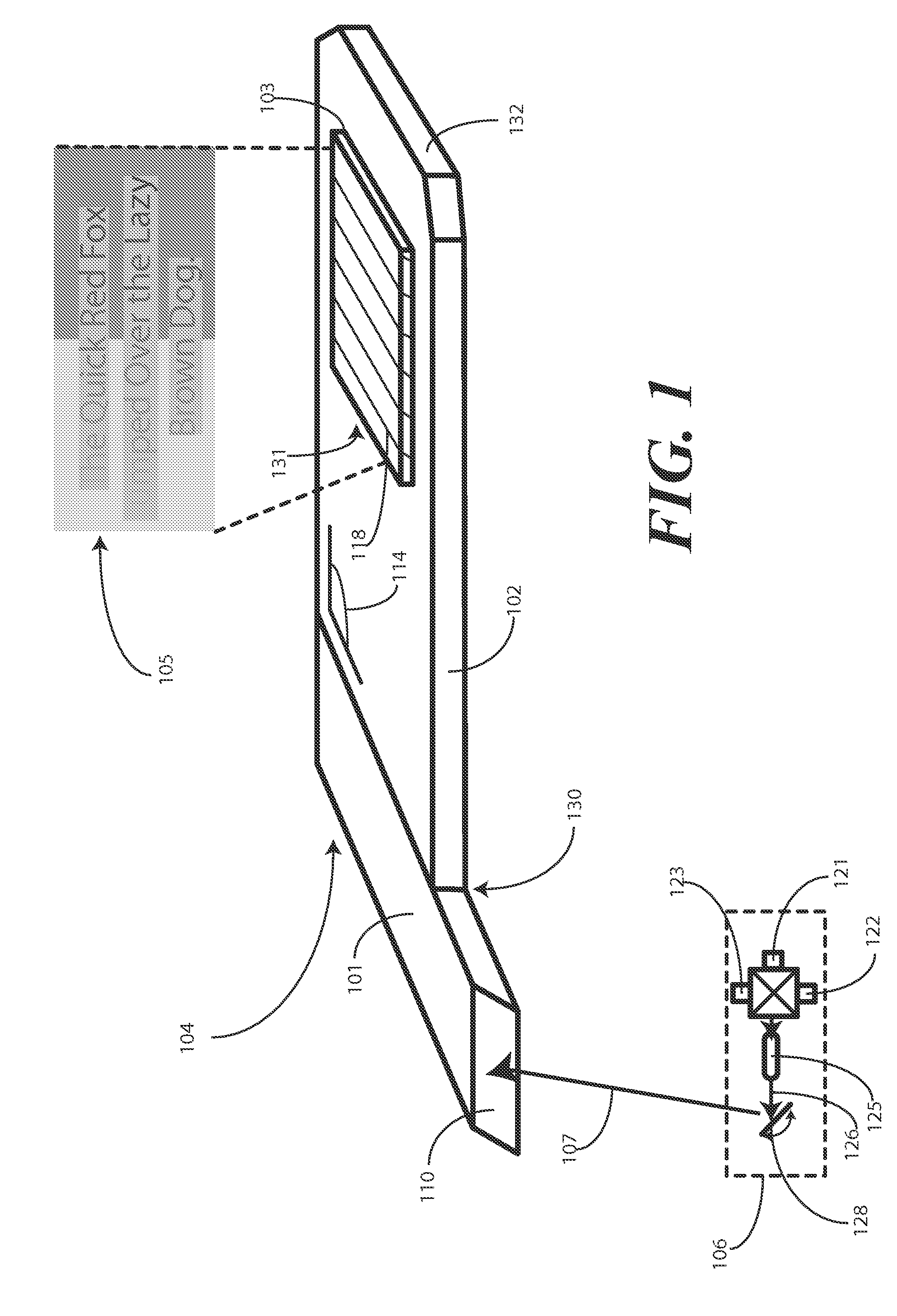
This desire to keep size to a minimum creates challenges, however, for the designer.
It can therefore be challenging for a substrate guided relay designer to create a display having a pupil that is much larger than the extent of the source.
Further, from a fabrication standpoint, it can be challenging to fabricate an input device or substrate of small dimensions with a high degree of precision generally associated with image guiding substrates.
Sometimes, this mismatched beam to input ratio can cause dark regions or gaps in the output image where little or no light is present.

Method used


Image

  • Substrate guided relay with homogenizing input relay
  • Substrate guided relay with homogenizing input relay
  • Substrate guided relay with homogenizing input relay

Examples


Embodiment Construction

[0021]Embodiments of the invention are now described in detail. Referring to the drawings, like numbers indicate like parts throughout the views. As used in the description herein and throughout the claims, the following terms take the meanings explicitly associated herein, unless the context clearly dictates otherwise: the meaning of “a,”“an,” and “the” includes plural reference, the meaning of “in” includes “in” and “on.” Relational terms such as first and second, top and bottom, and the like may be used solely to distinguish one entity or action from another entity or action without necessarily requiring or implying any actual such relationship or order between such entities or actions. Also, reference designators shown herein in parenthesis indicate components shown in a figure other than the one in discussion. For example, talking about a device (10) while discussing figure A would refer to an element, 10, shown in figure other than figure A.

[0022]Embodiments of the present inv...


PUM


Abstract

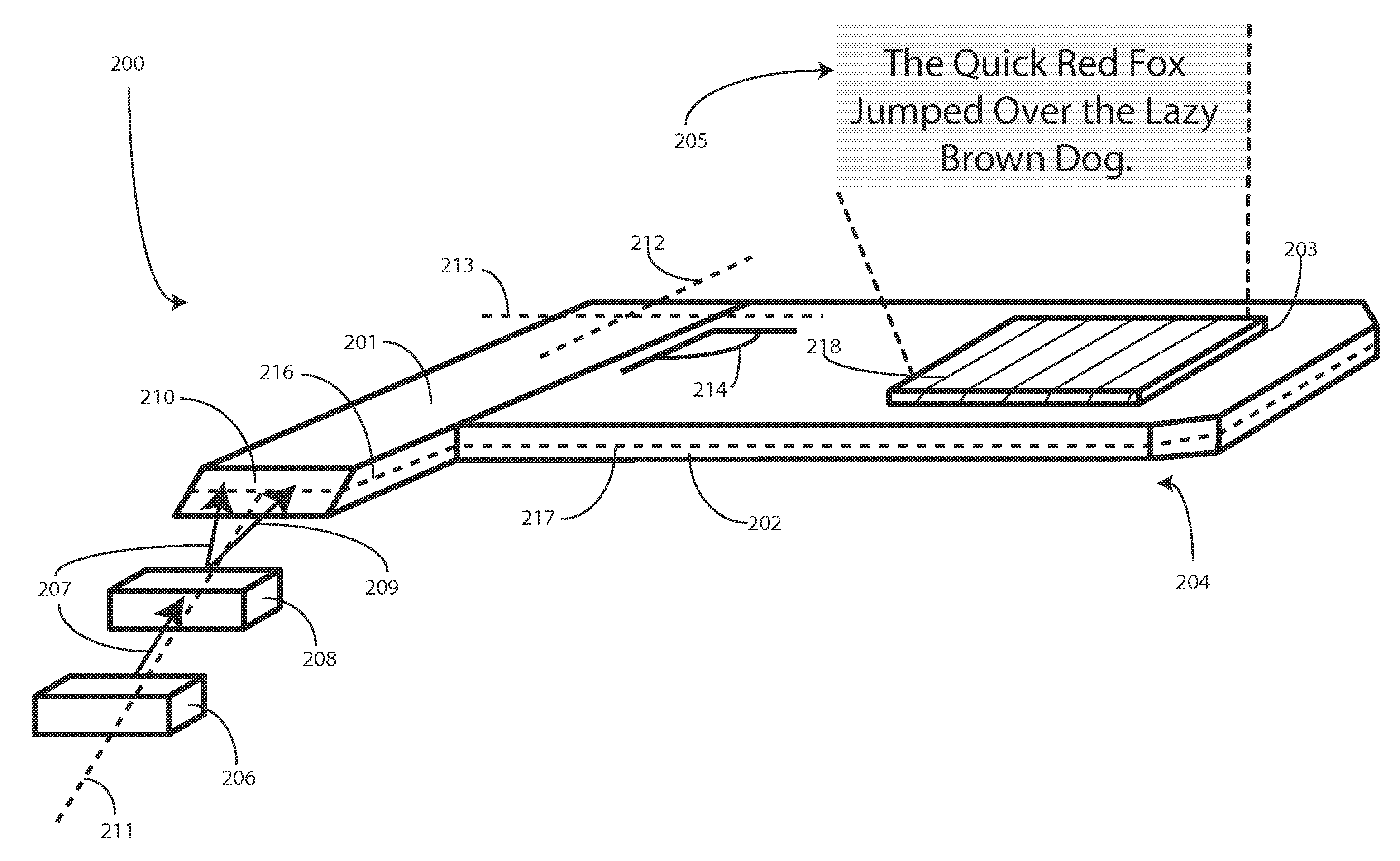
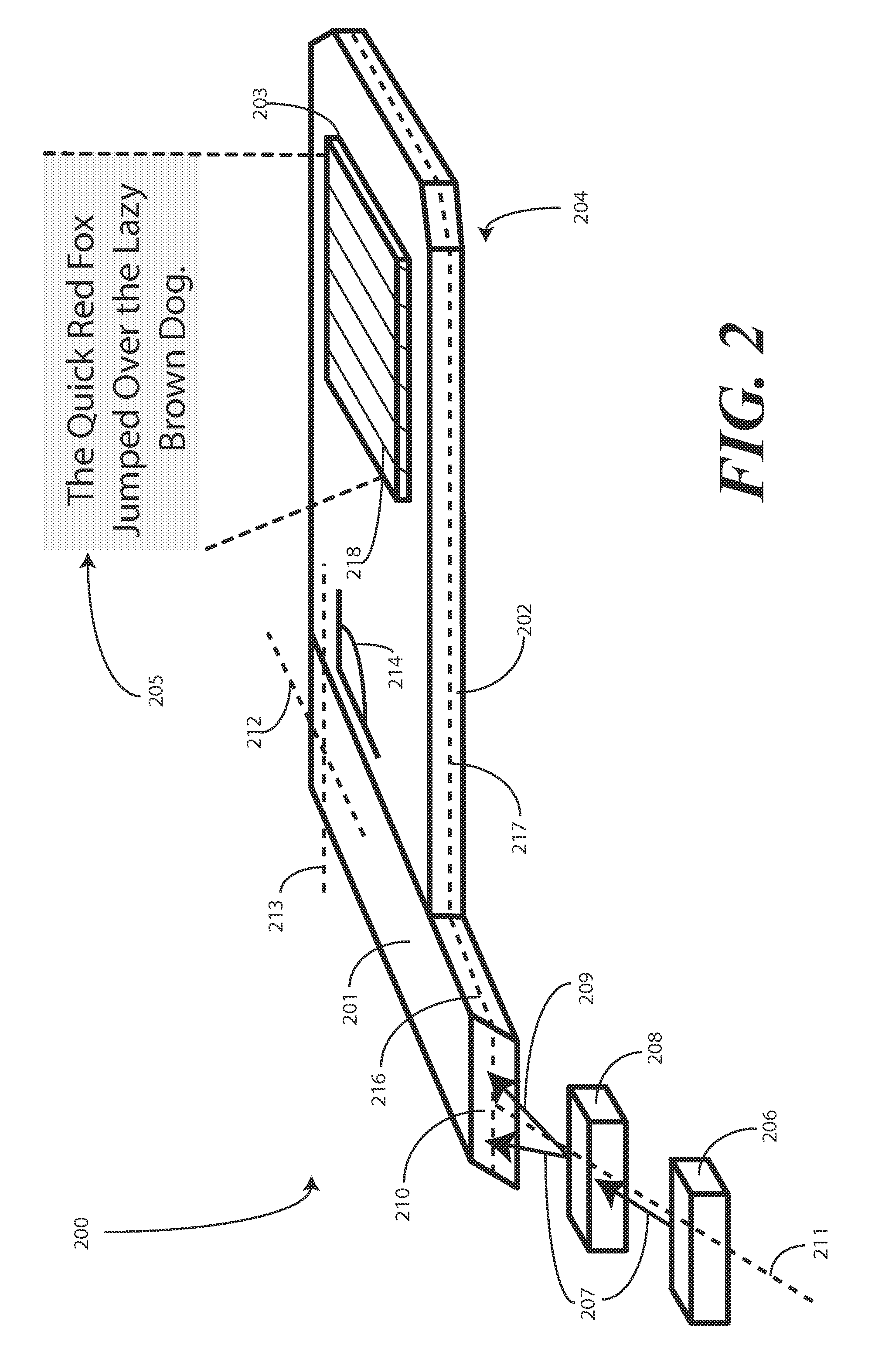
An optical relay system (200) includes a scanned light source (206) and a substrate guided relay (204). The substrate guided relay (204) includes an input coupler (201), an output coupler (203), and an optical substrate (202) disposed therebetween. A light homogenizing relay device (208) is disposed between the scanned light source (206) and the substrate guided relay (204). The light homogenizing relay device (208) is configured to receive a light beam (207) from the scanned light source (206). The light homogenizing relay device (208) makes at least one copy (209) of the light beam (207), and delivers the light beam (207) and the at least one copy (209) to a light receiving surface (210) of the input coupler (201), thereby effectively creating a larger input beam while retaining the angular spread of the initial light beam (207).

Description

BACKGROUND[0001]1. Technical Field[0002]This invention relates generally to optical relay systems, and more particularly to an optical relay system that includes a substrate guided relay and scanned light source, and which employs a homogenizing input relay device to make copies of an input light beam to provide a more uniform image output.[0003]2. Background Art[0004]Substrate guided relays are devices that transmit light rays from a source to a viewer. Generally, substrate guided relays are optical image transfer devices that include a substrate, which may manufactured from glass or fused silica, and which directs light from a relay input to a relay output. This light can be guided along its path by the optical transfer properties of the substrate. These optical transfer properties can additionally work in tandem with reflective or diffractive devices coupled to the substrate. The surfaces of the substrate can also work to direct the light to its intended destination. In many appl...

Claims


Application Information

Patent Timeline
IPC IPC(8): G02B6/32G02B6/26G02B6/42
CPCG02B6/0028G02B27/0938G02B27/0081G02B27/0172G02B6/0055G02B6/0056G02B6/006
Inventor DEJONG, CHRISTIAN DEAN
Owner MICROVISION
Learn More