Air bath with bypass vent

a technology of air vents and air baths, applied in bathing devices, light therapy, physical therapy, etc., can solve the problems of inoperable air system, rather complex air delivery system, and increasing cost, and achieve the effect of enhancing the bathing experien

Active Publication Date: 2009-11-10
KOHLER CO
View PDF20 Cites 7 Cited by
  • Summary
  • Abstract
  • Description
  • Claims
  • Application Information

AI Technical Summary

Benefits of technology

[0011]The invention provides an improved air delivery system for an air bath and an air bath incorporating the improved air delivery system. With the present invention, an enhanced bathing experience is achieved through a wider range of bubble densities.
[0016]The bypass vent also plays a vital role in protecting the blower from overheating, particularly when operating a lower speeds. Since the bypass valve is open to ambient air, if the back pressure from the water head in the basin is too high for positive air flow through the air outlets, all of the air from the blower can be redirected out of the bypass valve. Since the air in this case will be passing through a smaller passage than during normal operation, there will be somewhat more back pressure on the blower, albeit not enough to cause the blower to stall, or otherwise overheat and damage the blower. As mentioned, the problem with the water pressure head blocking flow through the air outlets is most likely to arise at a low flow volume / rate, especially when the water in the basin is high. With the bypass valve, the blower can operate at low speed without stalling or overheating. As mentioned above, this gives the user a wider range of bubbling effects, particularly more subtle, softer feeling bubbles.
[0017]In addition to protecting the blower, the bypass vent also reduces or prevents chattering of the check valve that can occur in closed systems when the back pressure is about equal to the pressure from the blower. By relieving back pressure, the check valve is quieted.
[0018]In other preferred forms, a filter, such as one or more mesh screens, can be used to cover the opening and break up the exiting air flow to lessen noise. The filter may diminish flow volume through the bypass vent somewhat, and thus should be considered when sizing the vent opening. An air manifold can be provided to couple the conduit to the air outlets. The air manifold can be one or more channels extending around, and possibly integral with, the side walls of the basin.
[0019]Moreover, an electronic control and control interface can allow the user to quickly and easily adjust the air to one or more zones (feet, back, shoulders, etc.) by the press of a button. The control can also be used to control the speed of the blower to adjust the air flow rate through the manifold, and thus the density and force of bubbles in the water.

Problems solved by technology

The air delivery systems in these patents are rather complex and may require a separate conduit for each air jet.
A damaged blower motor would render the air system inoperable, and replacement motors are expensive, and typically require a service call from a technician, further adding to the cost.
Even if damage to the motor could be avoided, it may still disrupt operation of the bubbling and destroy the air bath.
This somewhat limits the ability to provide soft, low density bubbling, without the use of supplemental tanks or accumulators, as described in U.S. Pat. No. 4,907,305.
And, since this is merely a protective measure, the system does not provide for more subtle bubbling.

Method used


Image

  • Air bath with bypass vent
  • Air bath with bypass vent
  • Air bath with bypass vent

Examples


Embodiment Construction

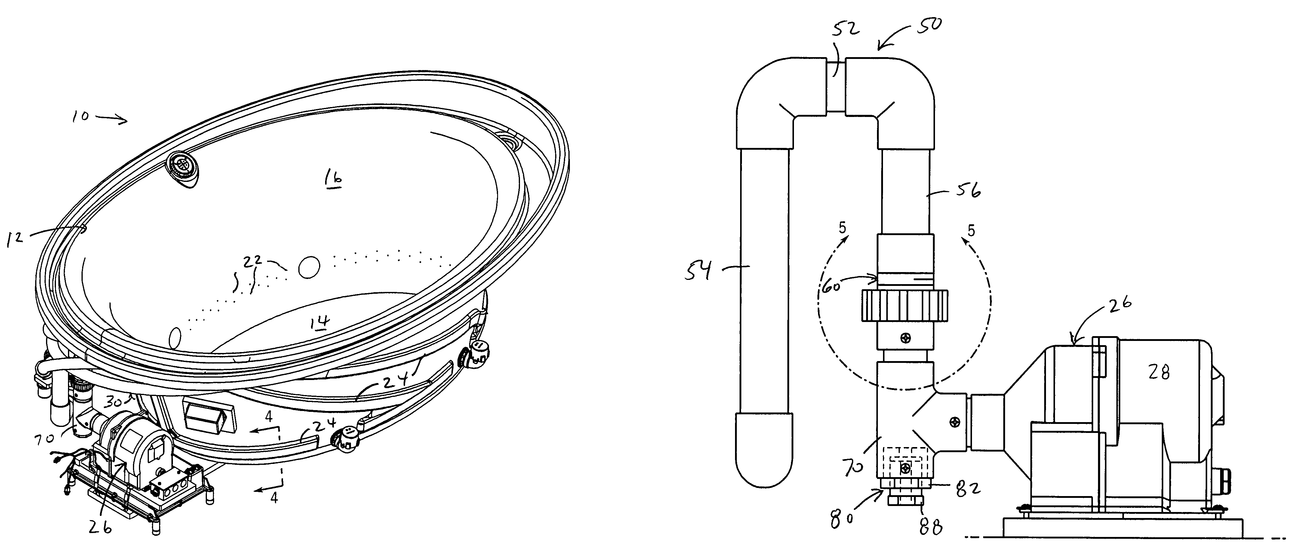
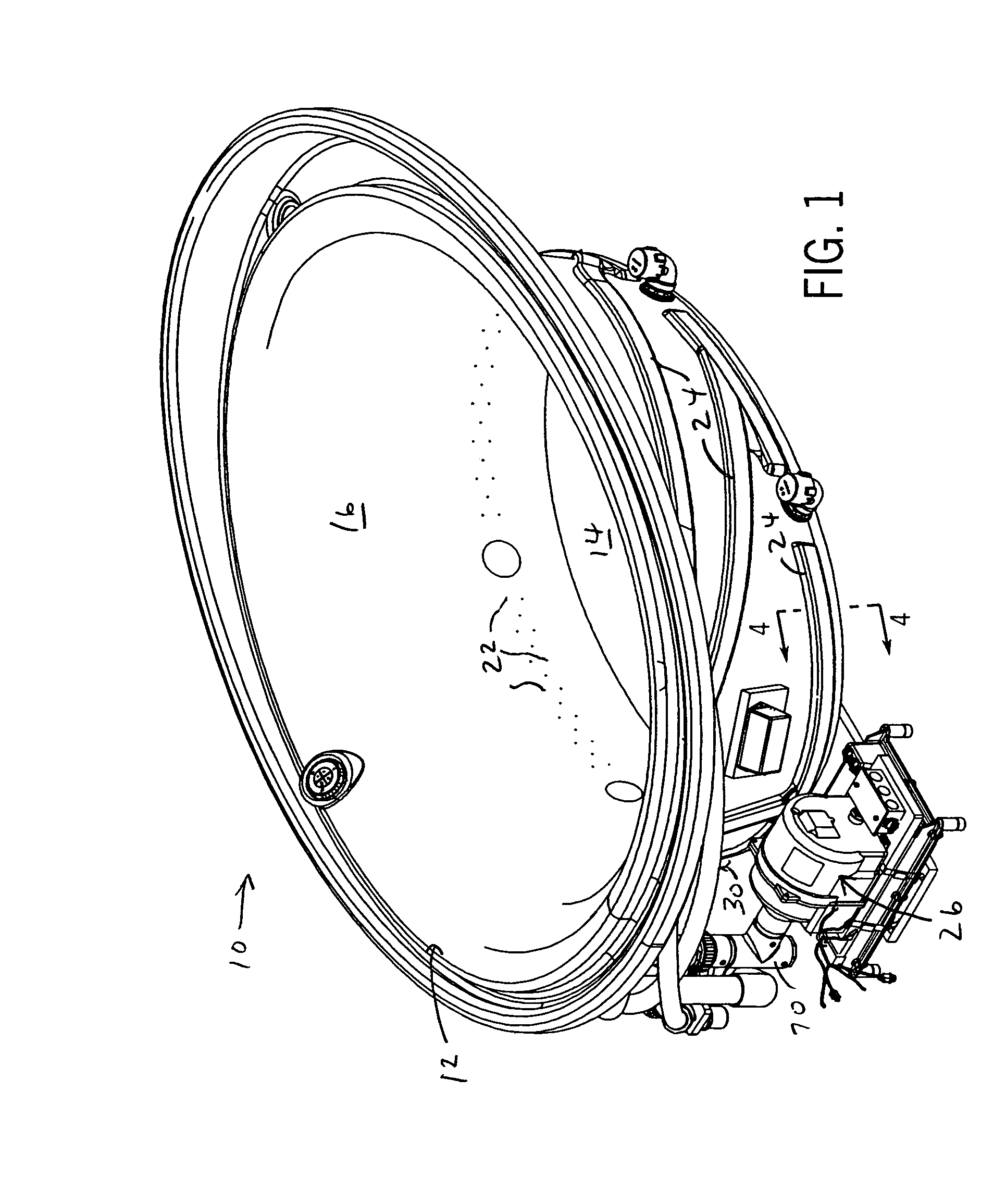
[0029]Referring to FIG. 1, an air bath 10 has a basin 12 defining a bottom 14 and contoured upright side walls 16. The bottom 14 has a drain opening with a drain stop controlled preferably remotely by an actuator having an overflow feature. It should be noted that while shown and described as a bathtub, the air bath 10 could be in other forms, such as a spa or swimming pool.

[0030]The side walls 16 of the basin 12 are formed with a plurality of openings defining air outlets 22, preferably in the lower half of the side walls 16. The air outlets 22 are simple round holes extending though the thickness of the side walls 16. The air outlets 22 are preferably sized and arranged in a special pattern designed to provide improved air flow for full body air induced hydrotherapy, as disclosed in the co-owned and co-pending U.S. patent application Ser. No. 10 / 774,123, filed on Feb. 6, 2004.

[0031]Briefly, the air outlets 22 are arranged in a plurality of lateral (or horizontal) rows, three are s...


PUM


Abstract

An air bath has air outlets extending around the side walls of the water basin. Air is delivered to the air outlets through a ring-like air manifold coupled to a blower by conduit. The conduit has a bypass vent that siphons off a portion of the air flow otherwise passing to the air outlets and maintains the blower in communication with ambient air. The air delivery system provides a wider range of bubble densities by allowing the blower to operate at lower speeds without overheating or stalling from back pressure arising from the pressure head of the water in the basin.

Description

CROSS-REFERENCE TO RELATED APPLICATIONS[0001]Not applicable.STATEMENT OF FEDERALLY SPONSORED RESEARCH OR DEVELOPMENT[0002]Not applicable.BACKGROUND OF THE INVENTION[0003]The present invention relates to bathtubs in which air is bubbled into the water, and in particular to air delivery systems for such bathtubs.[0004]Therapeutic water baths and pools are well-known. Spas or whirlpool tubs are common examples in which water streams from jets through the walls of the basin flow into the water beneath the surface, usually directed at muscle areas of a person's body, for example shoulders, back and thighs. The force from the jets “massage” the bather directly, as well as agitate the water, to provide therapeutic effects for other parts of the body not directly in the path of the jets. U.S. Pat. No. 6,185,757 discloses one such bath with water jets.[0005]Some tubs instead use air streams to agitate the water. U.S. Pat. Nos. 5,898,958 and 6,317,903 each disclose a tub that introduces air i...

Claims


Application Information

Patent Timeline
Patent Type & Authority Patents(United States)
IPC IPC(8): A61H33/06A61H33/02
CPCA61H33/02A61H33/60A61H33/6026A61H2033/023A61H2201/10A61H2033/0083A61H2033/0058A61N2005/0663
Inventor SWART, PETER W.BAUER, RONALD A.WANG, DIANA Q.
Owner KOHLER CO
Why Eureka
Try Eureka