
Stop rule for circular saw benches

a technology of stop rule and circular saw, which is applied in the direction of sawing apparatus, metal sawing apparatus, stock shearing machine, etc., can solve the problems of fence ruler, bulky and heavy, and too small space between hood and fence ruler

Inactive Publication Date: 2009-11-10
AIGNER GEORG
View PDF6 Cites 6 Cited by
  • Summary
  • Abstract
  • Description
  • Claims
  • Application Information

AI Technical Summary

Benefits of technology

"The present invention is a fence ruler for table circular saws that can be used in two positions, upright and horizontal, without needing to be attached to a protective hood. The fence ruler is small and can be easily positioned on the table of a circular saw. It includes a hollow body with a slide and catches that can be positioned in different ways for different workpiece sizes. The fence ruler can be easily attached to a clamping body on the machine table using an adapter and clamping connection body. The technical effects of the invention include improved flexibility, compact size, and ease of use for different workpiece sizes."

Problems solved by technology

Due to the fact that the saw blade must be covered upwards by an extractor hood, the space between hood and fence ruler may be too small to utilize a push-stick for advancing the work piece in the case of very narrow ledges.
This fence ruler, however, is very bulky and heavy, and can only be used in a standing position, the considerable disadvantage of which is that, when cutting narrow or lower ledges, a protective and extractor hood cannot be mounted above the saw blade due to insufficient space.
At the most, the extractor hood would have to be mounted above the guiding leg of the fence ruler, which would result in insufficient coverage of the saw blade and inadequate dust extraction.

Method used


Image

  • Stop rule for circular saw benches
  • Stop rule for circular saw benches
  • Stop rule for circular saw benches

Examples


Embodiment Construction

[0033]Detailed descriptions of embodiments of the invention are provided herein. It is to be understood, however, that the present invention may be embodied in various forms. Therefore, the specific details disclosed herein are not to be interpreted as limiting, but rather as a representative basis for teaching one skilled in the art how to employ the present invention in virtually any detailed system, structure, or manner.

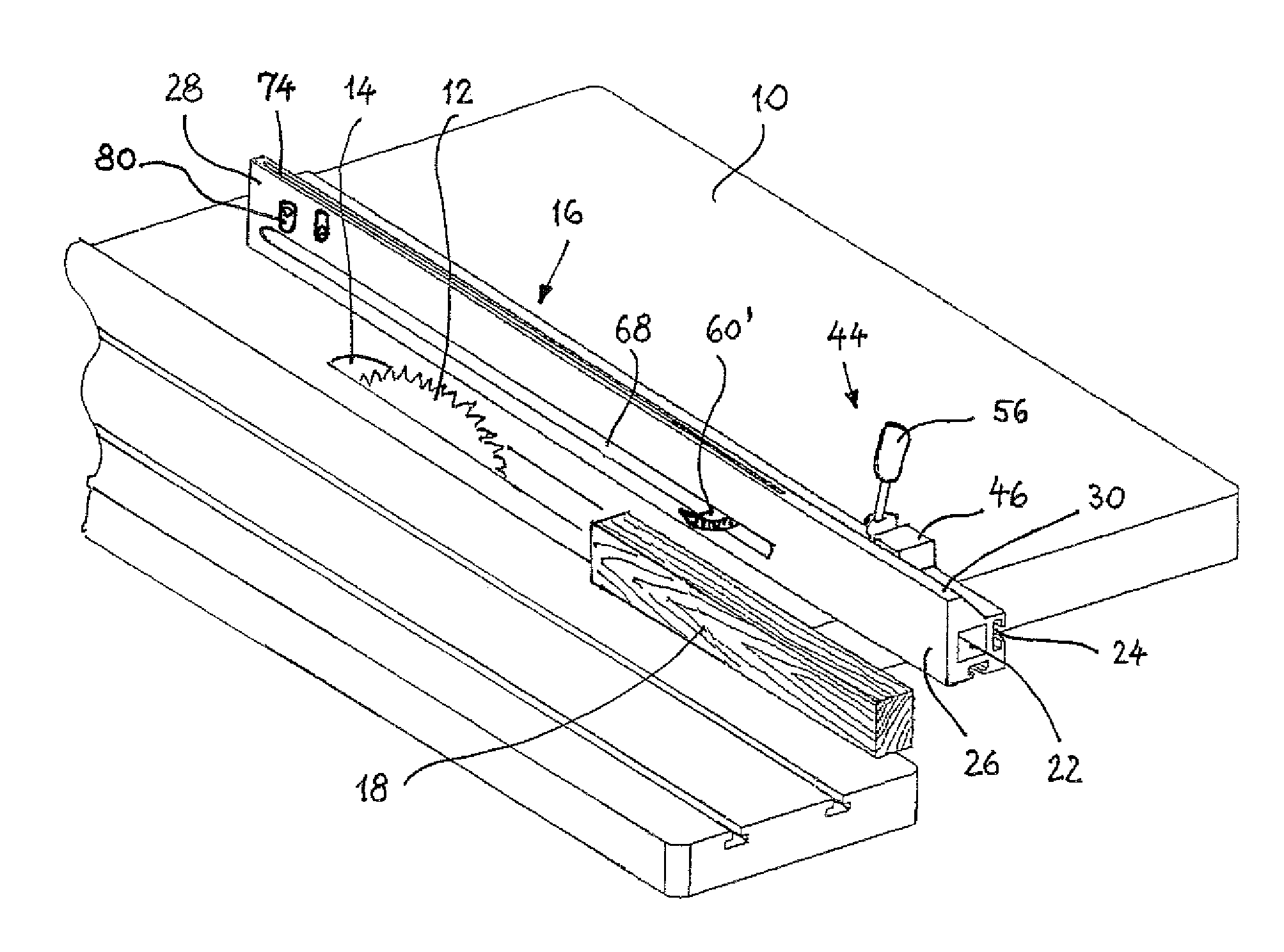
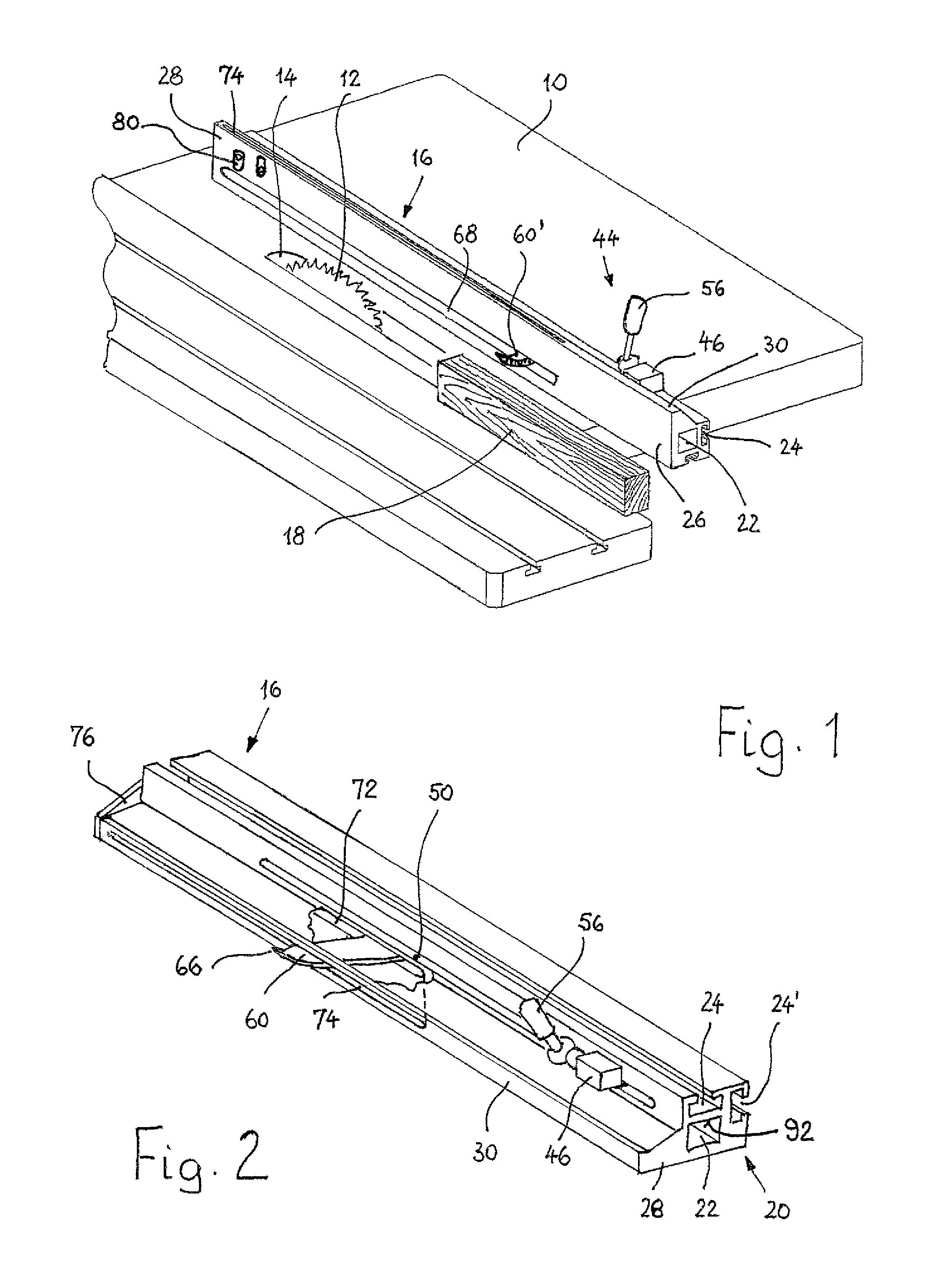
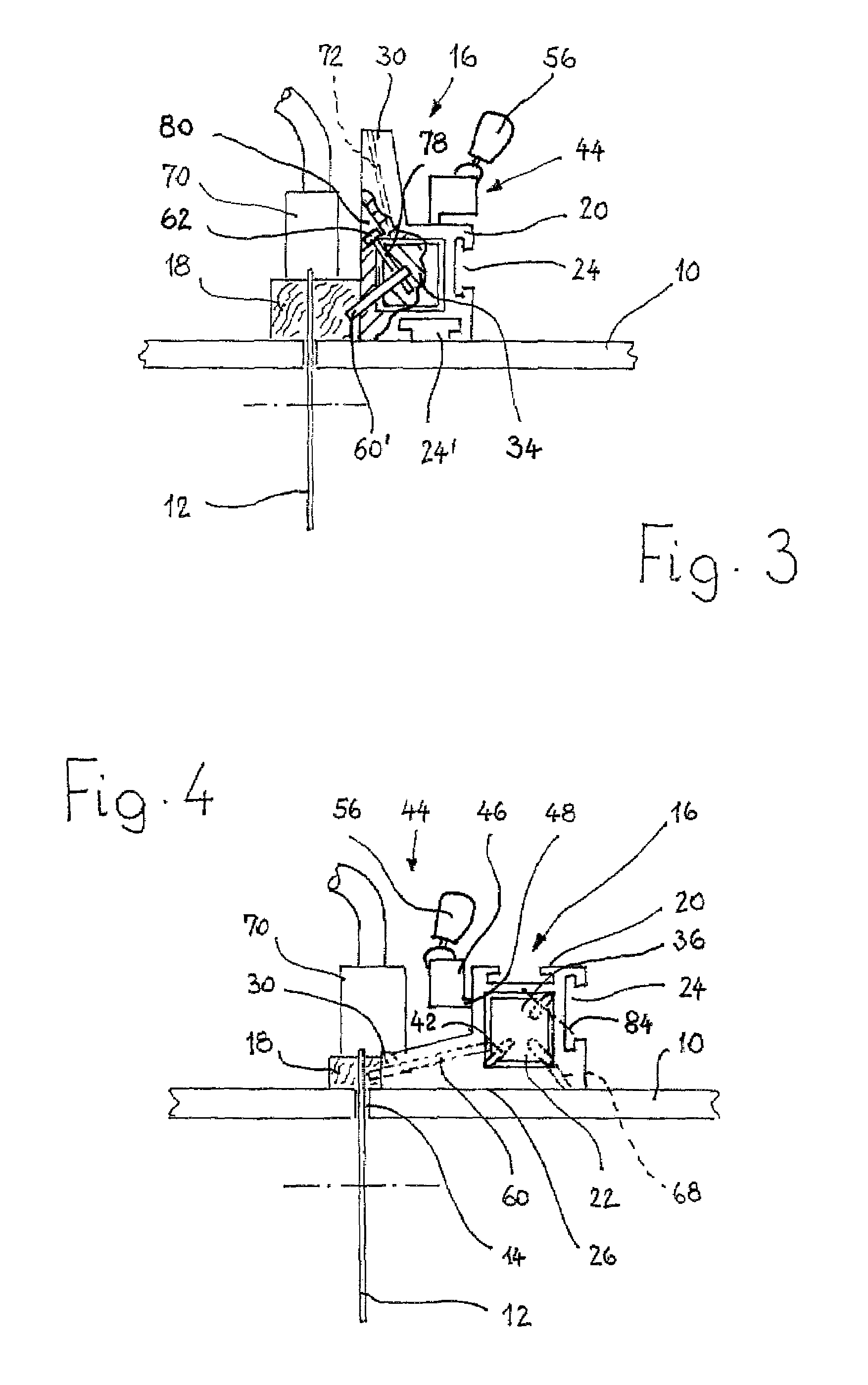
[0034]FIG. 1 shows a table circular saw with machine table 10 and saw blade 12, which protrudes upwards through opening 14 from machine table 10. On machine table 10, fence ruler 16 is mounted in a known manner, serving as a guide for ledge-shaped work piece 18.

[0035]FIGS. 1 through 4 show that fence ruler 16 consists of profiled hollow body 20, which extends in longitudinal direction and which shows a mostly rectangular or quadriform cross section with hollow space 22, also having a rectangular or quadriform cross section, as chosen by a user. On profiled hollow ...


PUM

PropertyMeasurementUnit
angleaaaaaaaaaa
offset angleaaaaaaaaaa
counter-weightaaaaaaaaaa

Abstract

A fence ruler for table circular saws includes a longitudinally extending profiled hollow body of mostly rectangular cross-section mountable onto a machine table. One side of the profiled hollow body is formed as a guiding leg with a protruding extension having on its front edge a guiding ruler for guiding lower work pieces. The guiding leg may also be positioned on the machine table to extend at a right angle from the same. A slide is positioned within the hollow space in the hollow body and is movable longitudinally from the outside. At least one catch protrudes from the hollow body and is guided through a longitudinal slot in the profiled hollow body that opens to the outside through an opening slot in the guiding ruler.

Description

BACKGROUND OF THE INVENTION[0001]1. Field of The Invention[0002]The present invention relates to a fence ruler for table circular saws that includes a longitudinally extending profiled hollow body of a mostly rectangular cross section. Means are formed on the profiled hollow body for the mounting onto a machine table, and one side of the profiled hollow body is formed as a guiding leg with a protruding extension having, on its front edge, a fence ruler for low work pieces. When the profiled hollow body lies horizontally on the machine table, the guiding leg protrudes upwards from the machine table in essentially perpendicular direction.[0003]2. Description of Related Art[0004]Fence rulers are used in table circular saws as guides for work pieces having sufficient width, for example, boards or planks, which are pushed forward manually. For smaller ledges, auxiliary means are used for as advancing the work pieces, such as the push-sticks designed by Aigner Sicherheitstechnik. Due to t...

Claims


Application Information

Patent Timeline
Patent Type & Authority Patents(United States)
IPC IPC(8): B23D45/06
CPCB27B27/02B27B25/10Y10T83/734Y10T83/773Y10T83/736Y10T83/6657Y10T83/741
Inventor AIGNER, GEORG
Owner AIGNER GEORG
Learn More