Button style cord connector

a cord connector and button-style technology, applied in the direction of connection, electrical apparatus, coupling device connection, etc., can solve the problems of interference with other parts in the box, inability to insert and remove the pull-out for re-use, and devices manufactured for non-standard sizes

Active Publication Date: 2009-11-10
THOMAS & BETTS INT INC
View PDF16 Cites 28 Cited by
  • Summary
  • Abstract
  • Description
  • Claims
  • Application Information

AI Technical Summary

Benefits of technology

[0017]An object of the invention is to provide a cord connector with a pliable shell having a wire passageway therethrough, a more rigid skeleton adjoining the shell also having a wire passageway therethrough, the skeleton having deflectable appendages which are deflected by the passage of a wire through the wire passageway, the deflectable appendages further restricting the removal of the wire back through the wire passageway; and whereby the pliable shell seals around the wire in the wire passageway and the skeleton provides strain relief to the wire in the wire passageway.
[0018]In another aspect of the invention, a cord connector assembly is provided that includes a rigid skeleton part characterized by a circumferential hoop, the skeleton part having an outer flange and at least a pair of inwardly jutting pronged cable supports adjacent the end, and at least a radially outwardly protruding tab on another distal end; and a pliable shell over-molded around at least a portion of the rigid skeleton part, the pliable shell having a center portion shaped to allow passage of a cable wire and provide strain relief to the cable wire but prevent passage of contaminants, wherein the protruding tab is configured to be pressed through a wall opening and the protruding tab and the outer flange are fashioned to jointly and directly impart more force on either sides of the wall for extension of the pliable shell.

Problems solved by technology

And thus, this design is useful for only a limited range of cable sizes, shapes and gauges.
This makes insertion and pullout removal for re-usage utterly impossible.
Also, the upright walls 35 extend about even with the wall catches (circumferential ridge), leading to a bulkier and thicker design, which could cause interference with other parts in the box.
Also, due the size of the device itself, the design fits only within certain standard opening sizes.
In fact, these devices are not manufactured for non-standard sizes.
In practice, moisture and debris can collect inside the device via this hole which is not desirable at all.
Thus, the device can not be used as a plug due to the device having two walls defining a debris-collecting storage space.
In tight spaces, or a wall where other side is not easily accessible, such installation can be frustrating.

Method used


Image

  • Button style cord connector
  • Button style cord connector
  • Button style cord connector

Examples


Embodiment Construction

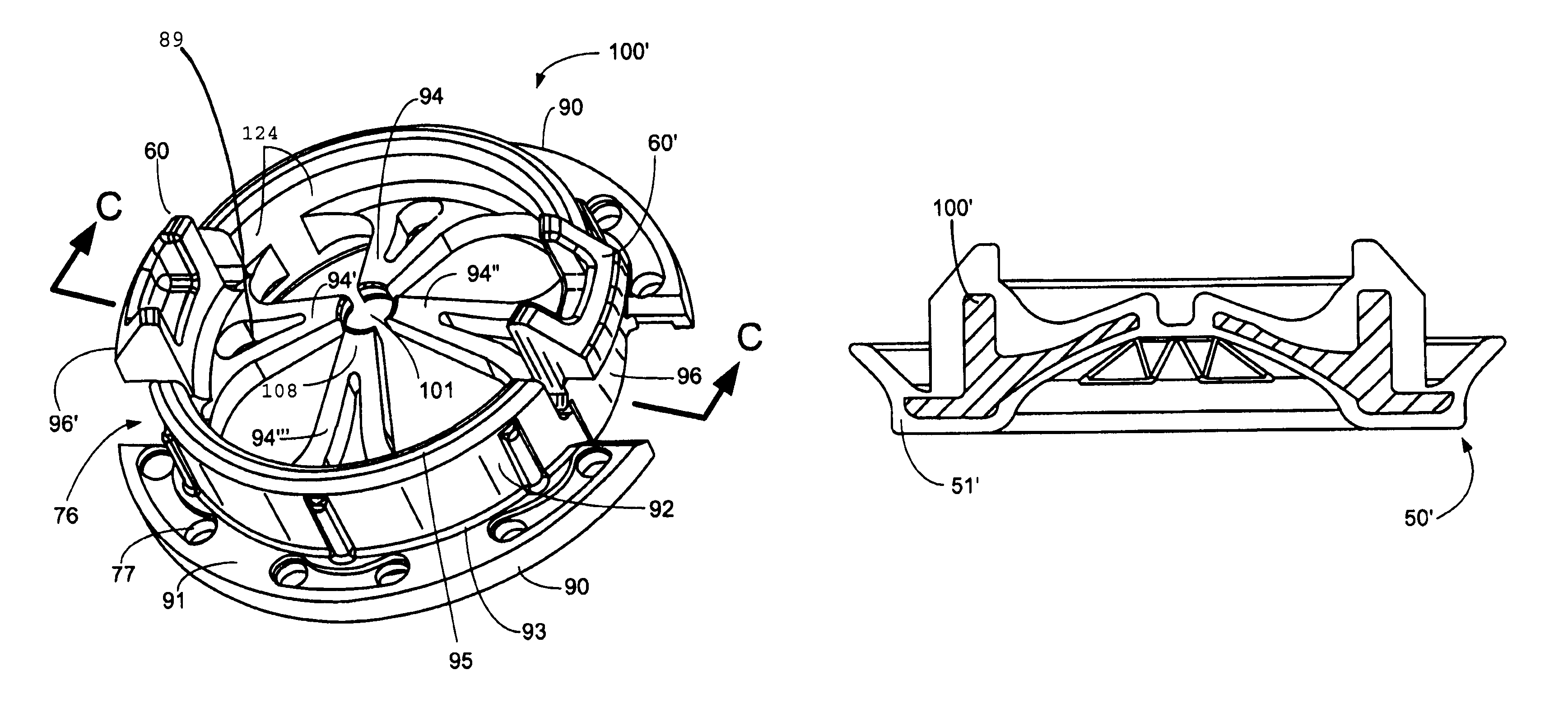
[0043]As can be seen in FIGS. 7 and 8, reference numeral 50 generally indicates a preferred embodiment of the invention, a button style cord connector that can be applied to a box 54 (of which only the indicated portion of wall 52 is shown) and accommodate a wire cable 58 through thereafter.

[0044]The connector 50 is generally a two-sided button-shape device with a substantially circular body having an insertion side portion 70 that is configured preferably with an axially short but radially wide center shaft. The tail side 80 can be configured with an overarching inverted mushroom-roof like projection which extends over the center shaft.

[0045]Although the insertion side portion 70 may vary in design, one particular embodiment can be designed as follows: The insertion side portion 70 can be designed as an axially compact pointed head 71 having a central egress side aperture 99. Because the pointed head 71 is typically designed to be less bulky, it does not protrude extensively into t...


PUM


Abstract

This invention pertains to a cord connector that both seals and provides strain relief automatically upon wire insertion. The cord connector comprises a wire passageway through a pliable shell which seals around both the wire inserted through the passageway as well as the knock-out or wall opening into which the connector is secured. A more rigid skeleton supports this shell and is provided with appendages which permit the wire to pass through the passageway but which block or resist any removal of the wire from the passageway. Preferably the shell is over-molded over the skeleton for ease of manufacture.

Description

[0001]This application is a continuation-in-part of U.S. application Ser. No. 11 / 491,221, filed Jul. 21, 2006, now U.S. Pat. No. 7,332,678 which claims the benefit of U.S. Provisional Application No. 60 / 701,415, filed Jul. 21, 2005.FIELD OF THE INVENTION[0002]This invention, in general, pertains to cord connectors for supporting electrical wire to a wall or a panel of an enclosure. More particularly, the present invention pertains to a connector for an electric cable providing both sealing and strain relief characteristics.BACKGROUND OF THE INVENTION[0003]Cord connectors for supporting electric wire passing through an aperture of an electrical enclosure or a wall are well known. These cord connectors are often used to protect wires or tubes passing through such apertures against wear or shock or both.[0004]U.S. Pat. No. 2,458,409 and U.S. Pat. No. 3,516,111 disclose a bushing-type connector member with integral spring-like fingers or supports radiating about an epicenter. These fing...

Claims


Application Information

Patent Timeline
Patent Type & Authority Patents(United States)
IPC IPC(8): H02G3/18
CPCH02G3/22H02G3/088H02G3/085H01R13/5205H01R13/5816
Inventor PYRON, ROGERYOSS, CRAIGCOLE, ANDREW C.
Owner THOMAS & BETTS INT INC
Why Eureka
Try Eureka