Electro-acoustic apparatus

Inactive Publication Date: 2009-11-10
YAMAHA CORP
View PDF19 Cites 2 Cited by
  • Summary
  • Abstract
  • Description
  • Claims
  • Application Information

AI Technical Summary

Benefits of technology

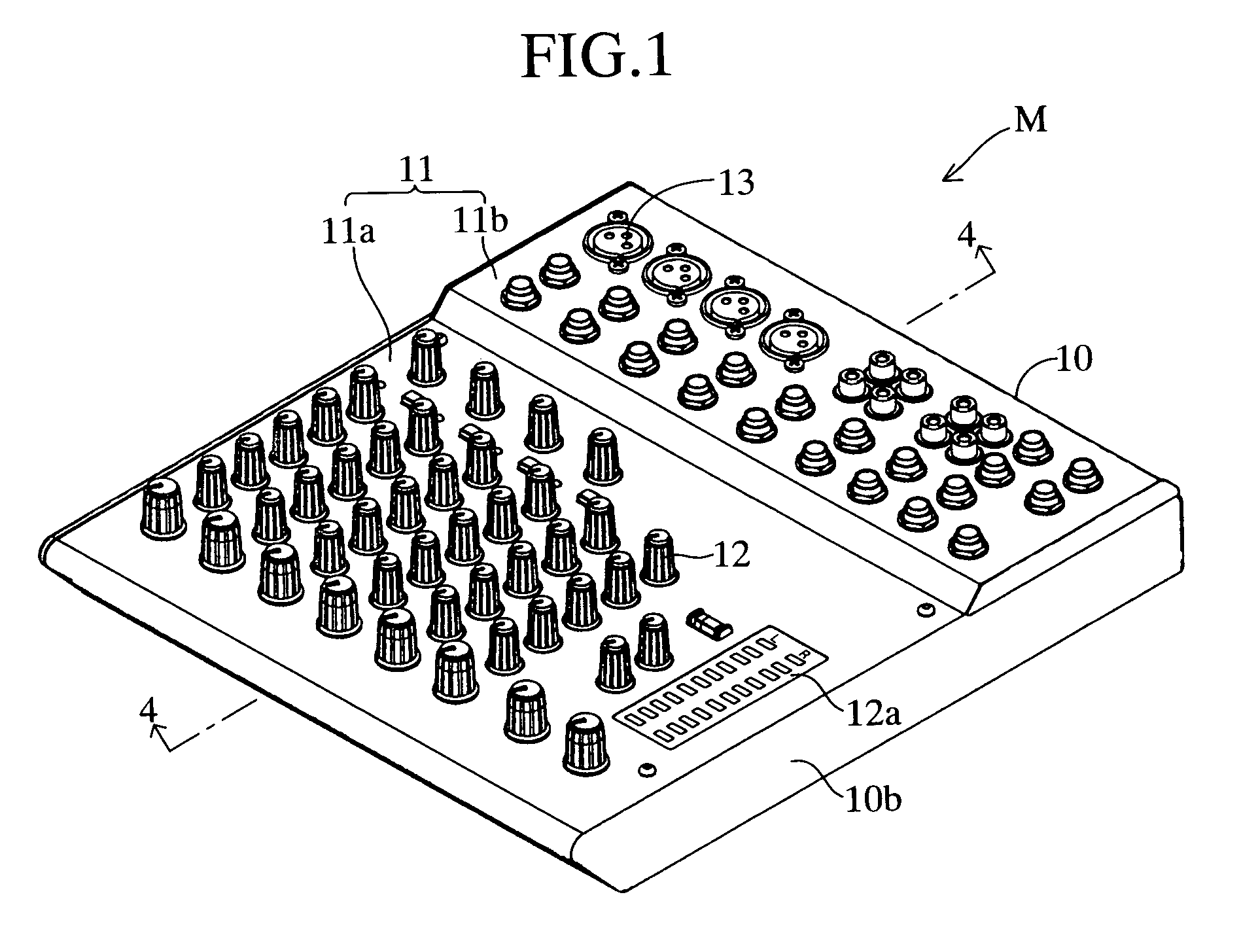
[0007]In order to achieve the above-described object, a structural feature of the electro-acoustic apparatus according to the present invention lies in the electro-acoustic apparatus being small enough to be transportable, wherein a multiplicity of operators are provided on a top surface of a body, internal threads are provided on a under surface of a body, and said internal threads are adapted to be engaged with external threads provided at the upper end of a stand, thereby allowing said electro-acoustic apparatus to be fixed on the upper end of the stand and supported by the stand.
[0008]Another structural feature of the electro-acoustic apparatus according to the present invention lies in the electro-acoustic apparatus having a multiplicity of terminals, connecting with a plurality of electronic apparatuses through cords removably connected to the terminals, and controlling the electronic apparatuses, the electro-acoustic apparatus being small enough to be transportable, wherein a multiplicity of operators controlling the external electronic apparatuses connected through the cords are provided on a top surface of a body, internal threads are provided on a under surface , and the internal threads are adapted to be engaged with external threads provided at the upper end of a stand, thereby allowing the electro-acoustic apparatus to be fixed on the upper end of the stand and supported by the stand.
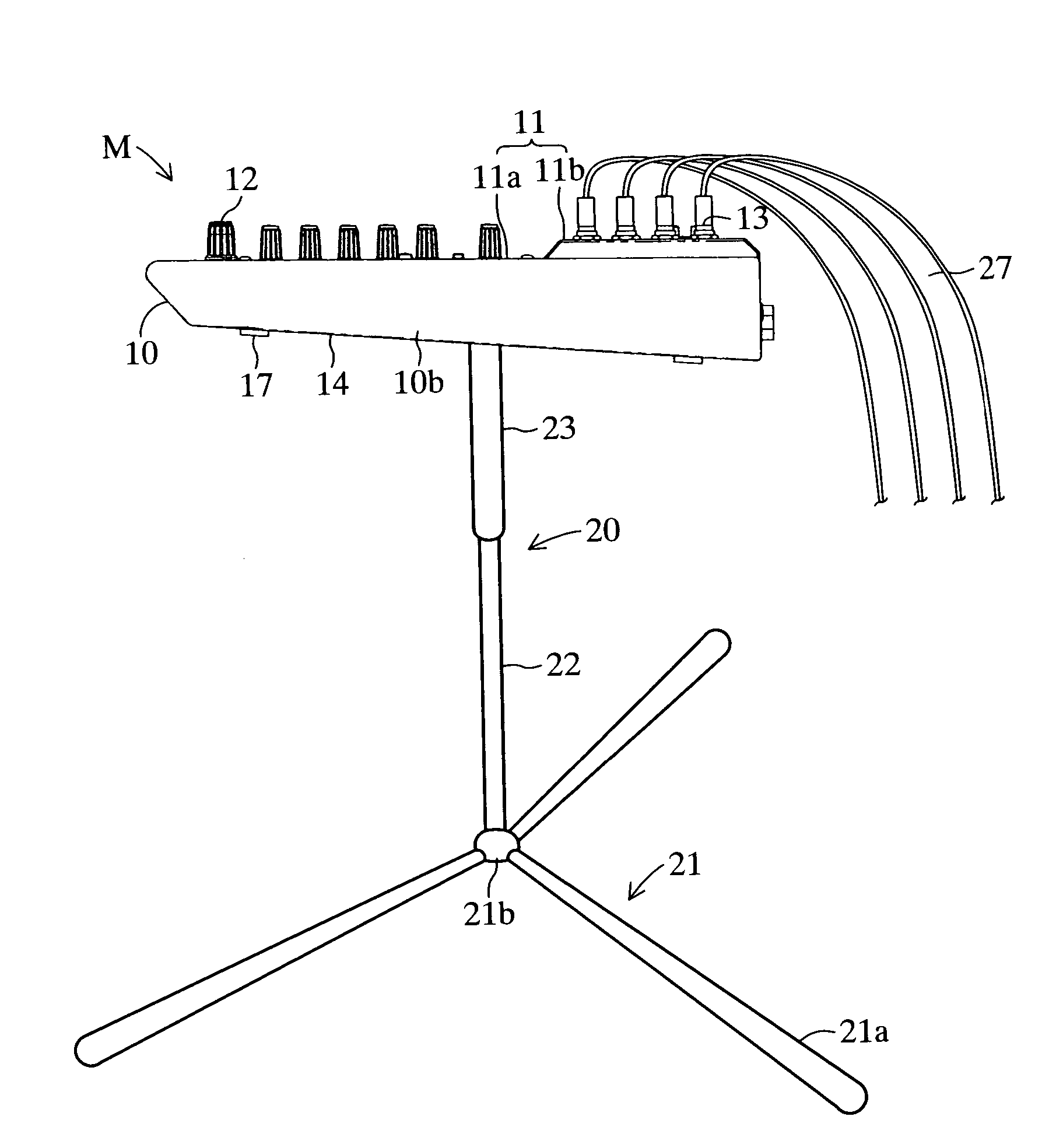
[0009]The electro-acoustic apparatus of the present invention structured as the above is adapted to be transportable and capable of being supported by the stand. As a result, the electro-acoustic apparatus as well as the stand can be carried to any desired place for use. Moreover, the electro-acoustic apparatus is provided with the internal threads on the under surface of the body, while the upper end of the stand is provided with the external threads adapted to engage the internal threads provided on the under surface. By the threaded engagement between the internal threads and the external threads, the electro-acoustic apparatus is adapted to be mounted on the upper end of the stand. Therefore, the electro-acoustic apparatus can be easily mounted and demounted on / from the stand.
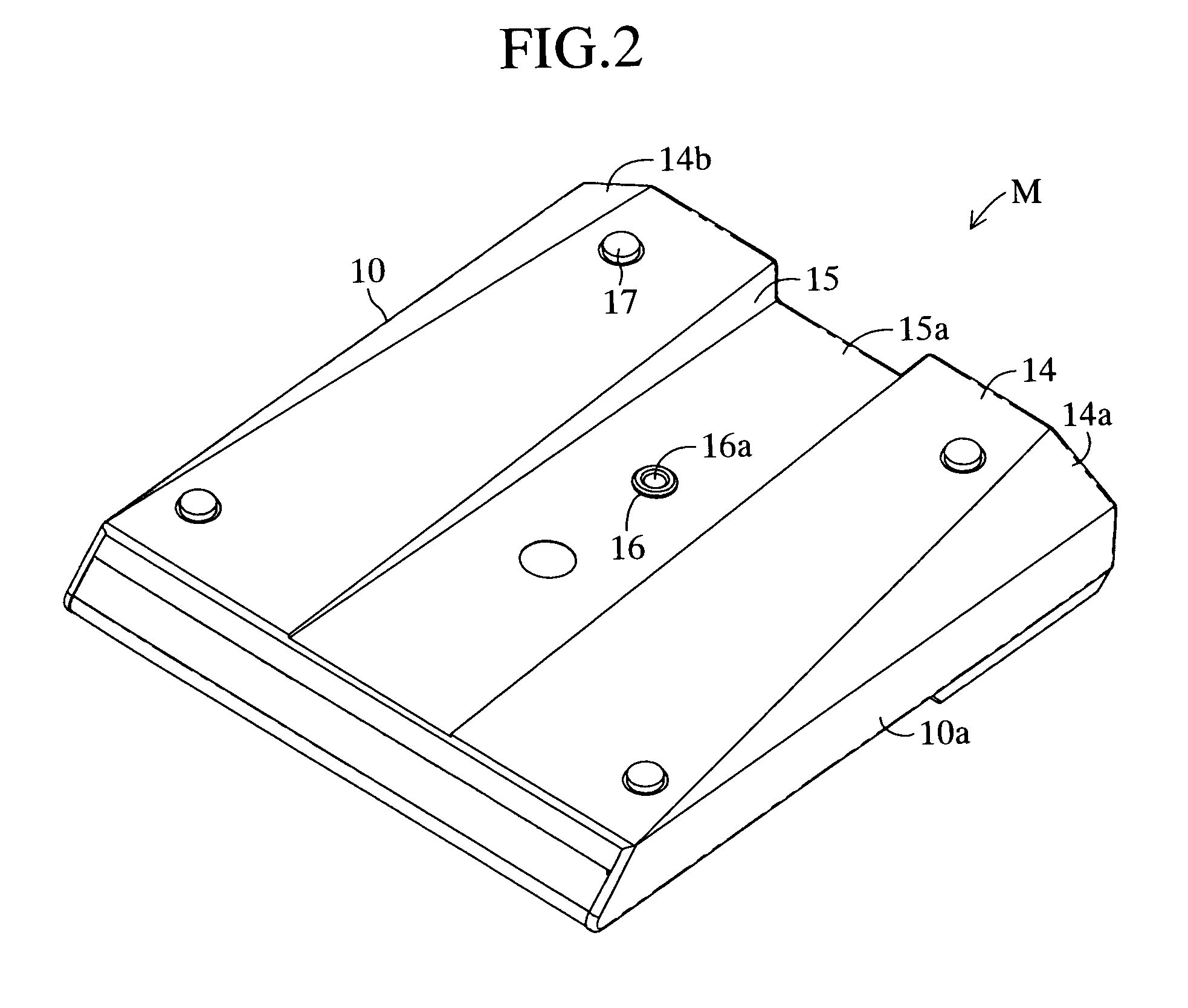
[0011]Another structural feature of the electro-acoustic apparatus according to the present invention lies in that a groove is provided on the reverse surface of the opposed surface of the body, the groove extending from one end of the reverse surface to the other end through the center of the reverse surface, and the internal threads are provided on the groove. Since the groove is provided on the reverse surface of the opposed surface of the body, the user can easily hold the electro-acoustic apparatus by placing his / her hand on the groove, and thereby easily carry about the electro-acoustic apparatus. Due to the groove, furthermore, the electro-acoustic apparatus increases in strength.
[0013]Because of the feature, for example, when the electro-acoustic apparatus is placed on a table and operated by a user sitting on a chair, the top surface of the electro-acoustic apparatus has a low front part and high rear part, providing the user with easy operability. When the electro-acoustic apparatus is mounted on a stand, on the other hand, the top surface of the electro-acoustic apparatus is kept on a horizontal line, and the user is allowed to operate the electro-acoustic apparatus in a comfortable position, looking down on the electro-acoustic apparatus from above in a standing position. Applicable as the stand are upright stands, which allow the electro-acoustic apparatus to maintain stability.
[0014]In this case, since the groove is formed on the under surface of the body from the front end of the under surface to the rear end such that the bottom base (the ceiling) of the groove is formed in substantially parallel with the top surface of the body, the top surface of the electro-acoustic apparatus can be kept on a substantially horizontal line when mounted on the stand. The internal threads are preferably provided at substantially the center of the groove or the position in the groove slightly moved off backward from the center of gravity of the electro-acoustic apparatus. When the bottom base of the groove is not in parallel with the top surface of the body, furthermore, the top surface of the electro-acoustic apparatus mounted on the stand can be kept substantially horizontal by forming the internal threads obliquely.

Problems solved by technology

However, the conventional base such as a table on which the electro-acoustic apparatus is placed is hardly transportable.

Method used


Image

  • Electro-acoustic apparatus
  • Electro-acoustic apparatus
  • Electro-acoustic apparatus

Examples


Embodiment Construction

[0025]An embodiment of the present invention will now be described with reference to the drawings. FIGS. 1 through 4 show an audio mixer M which is an electro-acoustic apparatus according to the present invention. FIG. 1 is a perspective view seen obliquely from above. FIG. 2 is a perspective view seen obliquely from below. FIG. 3 is a rear view. FIG. 4 is a cross sectional view of FIG. 1 taken along section lines 4-4.

[0026]A body 10 forming an outer part of the mixer M, which is formed by resin material, is a quadrangle on a plane. The body 10 is shaped like a box and designed to have a low front part (lower-left side of FIG. 1) and a high rear part (upper-right side of FIG. 1). On a top surface 11 of the body 10 there is provided a step which lowers the front part and hightens the rear part. The front part forms an operator mounting part 11a, and the rear part forms a terminal mounting part 11b. On the operator mounting part 11a there are mounted a plurality of operators 12 at giv...


PUM


Abstract

A bottom base 15a of a transportable mixer M is provided with internal threads 16a, while the upper end of a stand 20 is provided with external threads 25a which engage the internal threads 16a. The mixer M is adapted to be mounted on the stand 20 by the threaded engagement between the internal threads 16a and external threads 25a. Furthermore, a groove 15 is provided on an under surface 14 of the mixer M, the groove 15 extending from one end of the under surface 14 to the other end through the center. On the groove 15 there are provided the internal threads 16a. The mixer M is formed to have a low front part and a high rear part, such that a top surface 11 of the mixer M has a low front part and a high rear part when placed on a table 26, and stays on a substantially horizontal position when mounted on the stand 20. As a result, a transportable electro-acoustic apparatus capable of being fixed on and supported by a stand is provided.

Description

BACKGROUND OF THE INVENTION[0001]1. Field of the Invention[0002]The present invention relates to an electro-acoustic apparatus comprising a mixer, recorder, or the like which can be fixed on and supported by a stand.[0003]2. Description of the Related Art[0004]Conventional electro-acoustic apparatuses such as audio mixers and recorders are placed on a base such as a table when they are used (e.g. see Japanese Registered Utility Model No. 3009699).[0005]When an electro-acoustic apparatus is reduced in size and weight in order to make it transportable, a supporting member such as a base which supports the electro-acoustic apparatus is also required to be transportable. However, the conventional base such as a table on which the electro-acoustic apparatus is placed is hardly transportable.SUMMARY OF THE INVENTION[0006]The present invention was accomplished to solve the above-described problem, and an object thereof is to provide a transportable electro-acoustic apparatus which can be f...

Claims


Application Information

Patent Timeline
IPC IPC(8): H04R1/02G10H1/32
CPCG10H1/32
Inventor HABA, DAISUKE
Owner YAMAHA CORP
Why Eureka
Try Eureka