Membrane press

Inactive Publication Date: 2007-01-04
MEIER VAKUUMTECHN
View PDF3 Cites 12 Cited by
  • Summary
  • Abstract
  • Description
  • Claims
  • Application Information

AI Technical Summary

Benefits of technology

[0009] The invention aims at improving a membrane press of the aforementioned type such that a long service life of the membrane is achieved and that the membrane can be replaced in such an easy manner that the time saved is considerable.
[0010] The embodiment according to the invention of the holding elements is advantageuos in that, on due membrane replacement which must, in practice, usually be carried out approximately every two weeks or on an initial insertion of the membrane in the membrane press, the membrane can be manually removed from the holding elements without any tools and can also be located again without the use of any additional tool. To be located, the membrane can initially be inserted in the membrane press without the holding elements according to the invention. Thereafter, a single operator can then very quickly bring the holding elements, one after the other, in engagement with the membrane edge without using any tools. As a result, the time saved is considerable wherein, surprisingly, the membrane replacement with the holding elements according to the invention has turned out to take only about a quarter of the time required for a conventional holder with a plurality of screws which must be unscrewed and / or tightened by means of additional tools, for example by means of a wrench.

Problems solved by technology

Since the membrane must be exchanged relatively often during operation of membrane presses or laminators, this is disadvantageous in that comprehensive assembly work taking relatively long time is required, because an accordingly high number of screwed connections must be disconnected and resecured secured after the old membrane has been removed and the new membrane has been inserted.
The membrane, however, is disadvantageous in that it must be assembled outside of the membrane press by attaching the clamping strips to the membrane beforehand.
This is relatively difficult because the surfaces concerned are large and the membrane and the clamping strips are relatively heavy.
The known state of the art is, furthermore, disadvantageous in that the membrane comprises holes at its edge, for example for passing the screws through the holes.
These holes, however, weaken the membrane edge, with the result that the holes are a frequent starting point of cracks which might completely destroy the membrane.

Method used


Image

  • Membrane press
  • Membrane press
  • Membrane press

Examples


Embodiment Construction

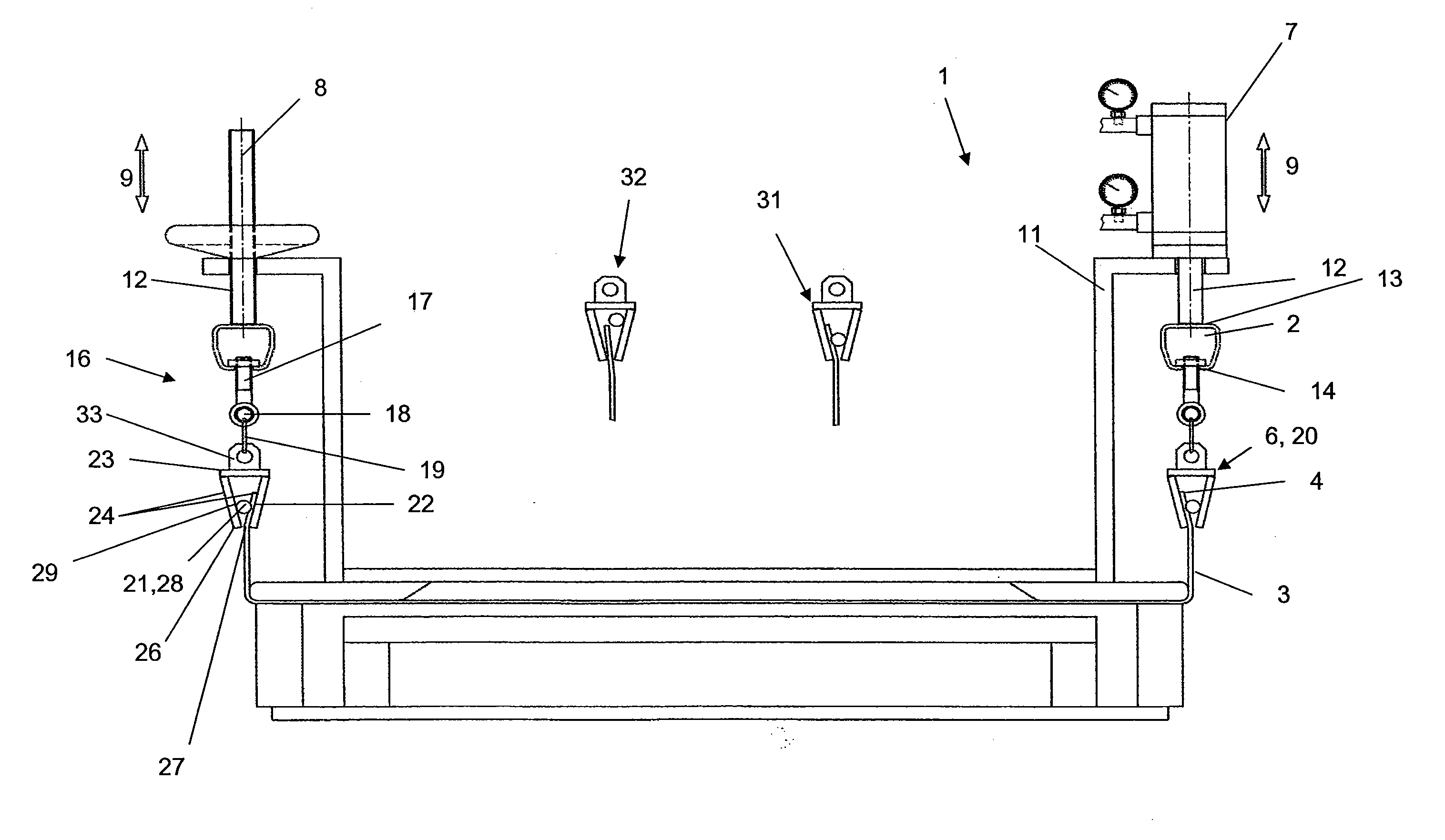
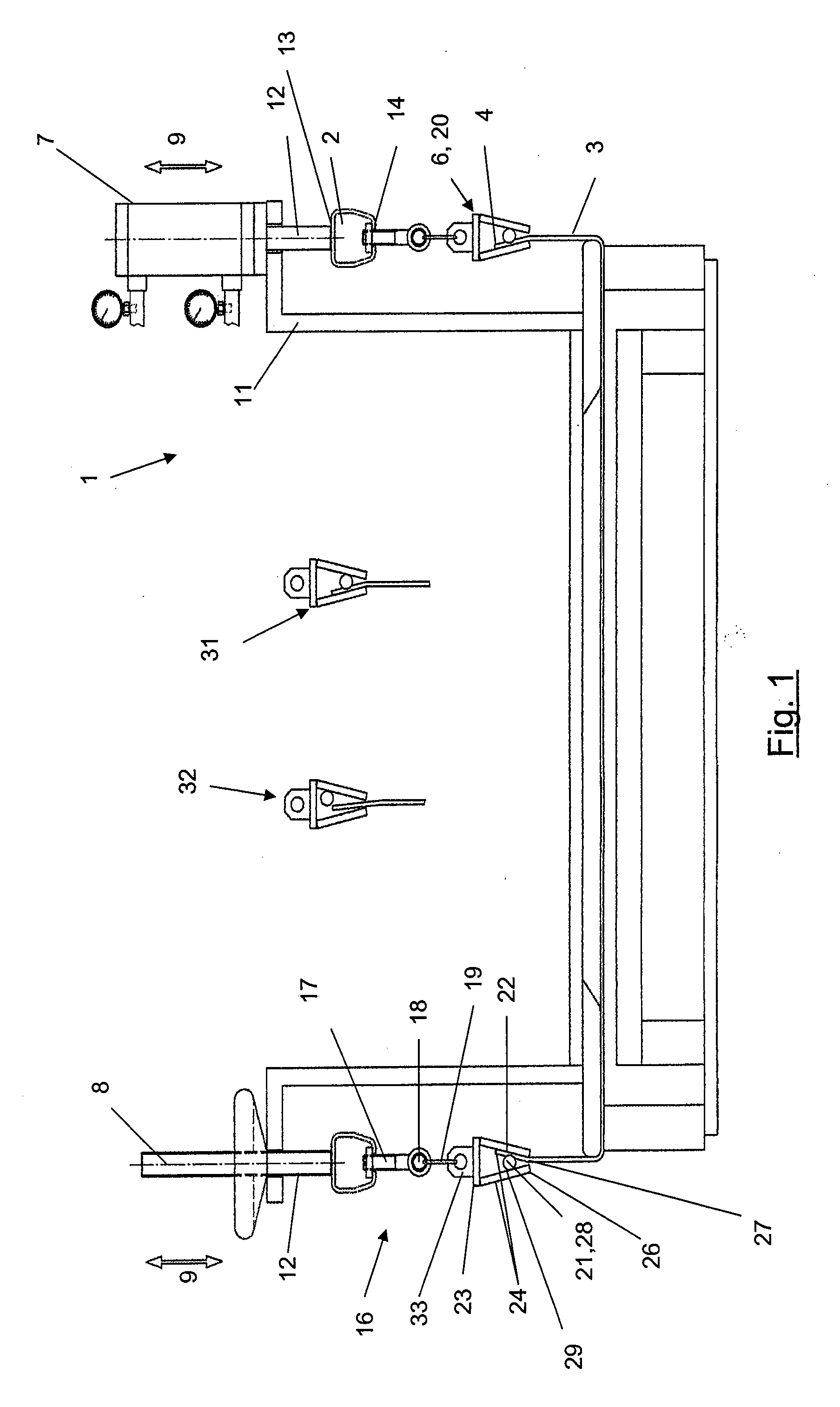
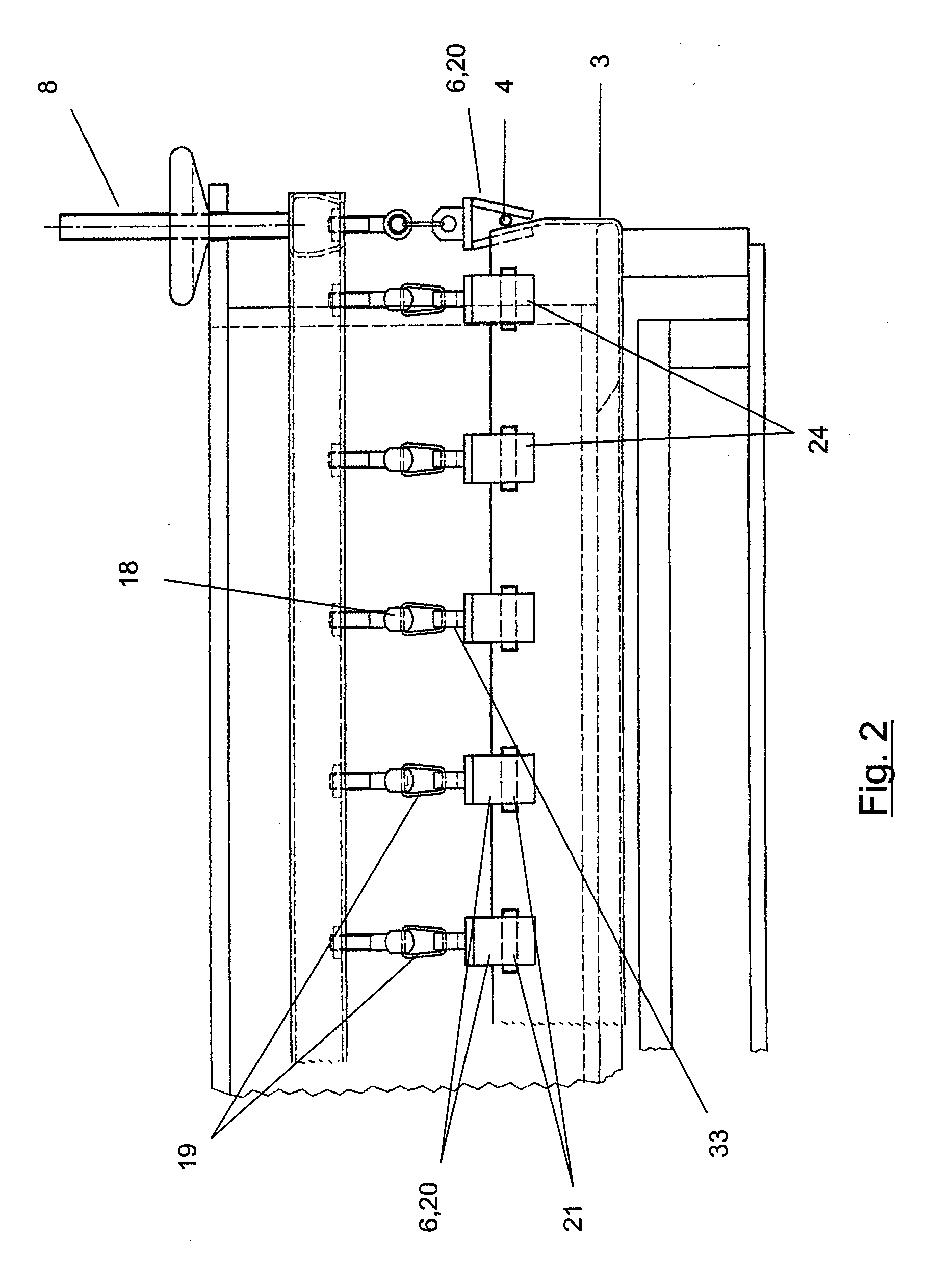
[0046]FIG. 1 shows a membrane press 1 comprising a holding frame 2. With its peripheral region 4, a membrane 3 can be located on and removed from the holding frame 2 via holding elements 6. The holding elements 6 are designed such that the membrane 3 can be removed and located without any tools.

[0047] The holding frame 2 is connected to adjusting devices 7, 8 such that the holding frame 2 can be adjusted in a clamping direction (double arrow 9).

[0048] For example, the adjusting devices 7, 8 can be designed as a pneumatic cylinder 7 or as a spindle 8. The exemplary embodiment illustrated in FIG. 1 shows both types of adjusting devices 7, 8, that is, on the one hand, the manually activated spindle and, on the other hand, the adjusting device 7 with a power drive (pneumatic cylinder). As a matter of course, it is also possible to use adjusting devices 7, 8 of the same kind in each case.

[0049] The adjusting devices 7, 8 are mounted to a rigid component 11 of the membrane press 1 or l...


PUM

PropertyMeasurementUnit
Angleaaaaaaaaaa
Distanceaaaaaaaaaa
Perimeteraaaaaaaaaa

Abstract

A membrane press including at least one holding frame, wherein a membrane is, at its peripheral region, located on and removed from the holding frame by holding elements, wherein the holding elements are designed such that the membrane is located thereon and removed therefrom without any tools. A first membrane press has holding elements designed with two clamping surfaces in the manner of a claw, wherein a clamping bolt is assigned to the clamping surfaces so that the membrane is located in a force-locking manner, wherein the membrane is clamped between the clamping bolt and one of the clamping surfaces. A second membrane press includes a holding element designed in a buckle-like manner in the form of one of a buckle lock, a clamping lock, a spring clip, a sliding web lock, an eccentric lock and a belt clamp.

Description

BACKGROUND OF THE INVENTION [0001] The present invention relates to a membrane press comprising at least one holding frame, wherein a membrane can, at its peripheral region, be located on and removed from the holding frame by means of holding elements, wherein the holding elements are designed such that the membrane can be located thereon and removed therefrom without any tools. [0002] Such membrane presses, in particular laminators, are known in the art. [0003] DE 30 17 273 discloses a membrane molding press with a pressure chamber that is open towards one side, comprising a membrane loosely covering the open side of the pressure chamber while the press is open, the membrane being located on the outside of the pressure chamber. The membrane molding press comprises a counter plate positioned opposite to the open side of the pressure chamber and a drive for placing the counter plate and the pressure chamber adjacent to each other in a force-locking manner. Furthermore, the membrane p...

Claims


Application Information

Patent Timeline
IPC IPC(8): B01D29/00
CPCB30B5/02
Inventor STEVENS, HANS-GERD
Owner MEIER VAKUUMTECHN
Why Eureka
Try Eureka