Parameter Controlling Apparatus

Active Publication Date: 2012-12-27
YAMAHA CORP
View PDF6 Cites 0 Cited by
  • Summary
  • Abstract
  • Description
  • Claims
  • Application Information

AI Technical Summary

Benefits of technology

[0007]The present invention was accomplished to realize the switching of target parameter by a simple configuration and easy operability. As for descriptions for respective constituents of the present invention described below, numbers corresponding to components of a later-described embodiment are given in parenthesis for easy understanding. However, the respective constituents of the present invention are not limited to the corresponding components indicated by the numbers of the embodiment.
[0010]Furthermore, the operating area includes a display device (401) for displaying a position corresponding to a current value of the parameter; the content of the input operation of the operating area is information which relates to depressing operation of the operating area and represents a position at which the operating area has been depressed and released with a finger; and the parameter value change portion increases or decreases the value of the target parameter in accordance with a relation between the position represented by the information relating to the depressing operation and the position displayed by the display device.
[0015]Without a plurality of operating elements and an additional display for instructing the switching of a target parameter, the present invention achieves the switching of target parameter by the simple configuration and realizes the easy operability.

Problems solved by technology

In order to switch a parameter assigned to a touch type operating element, schemes employed in the above-described Japanese Unexamined Patent Publication No. 61-15198 and Japanese Unexamined Patent Publication No. 2010-233005 require a plurality of operating elements for instructing the switching and a display in addition to the touch type operating element, resulting in a complicated configuration and user-unfriendliness.

Method used


Image

  • Parameter Controlling Apparatus
  • Parameter Controlling Apparatus
  • Parameter Controlling Apparatus

Examples


Embodiment Construction

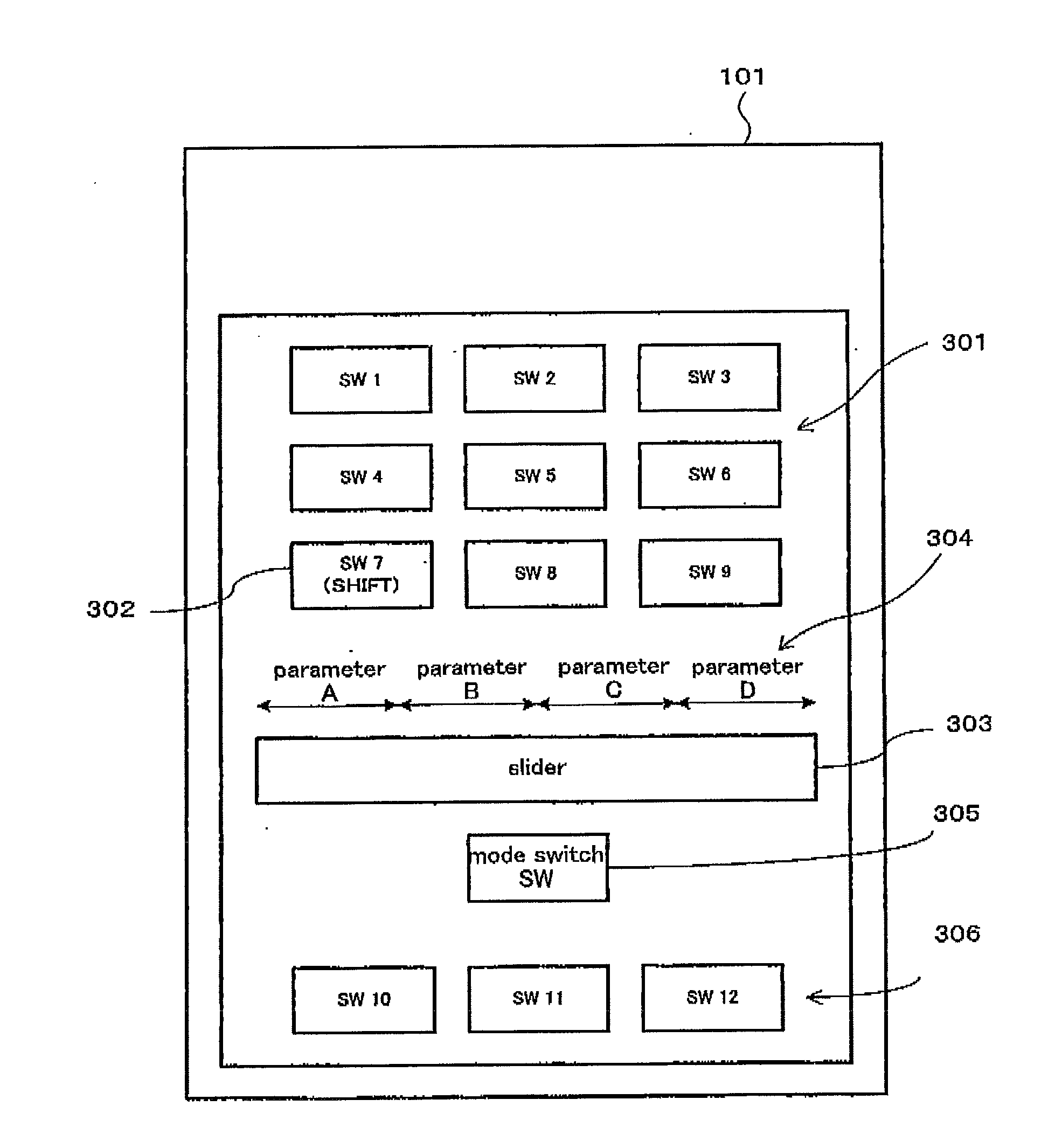
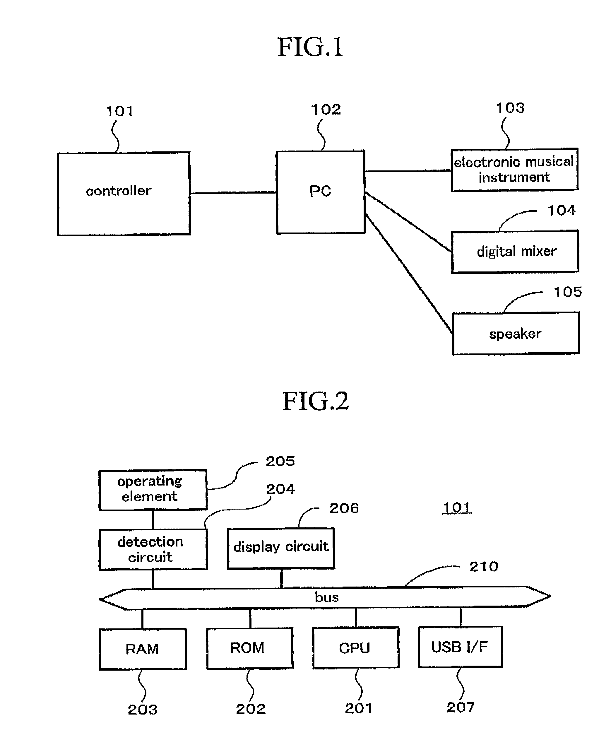
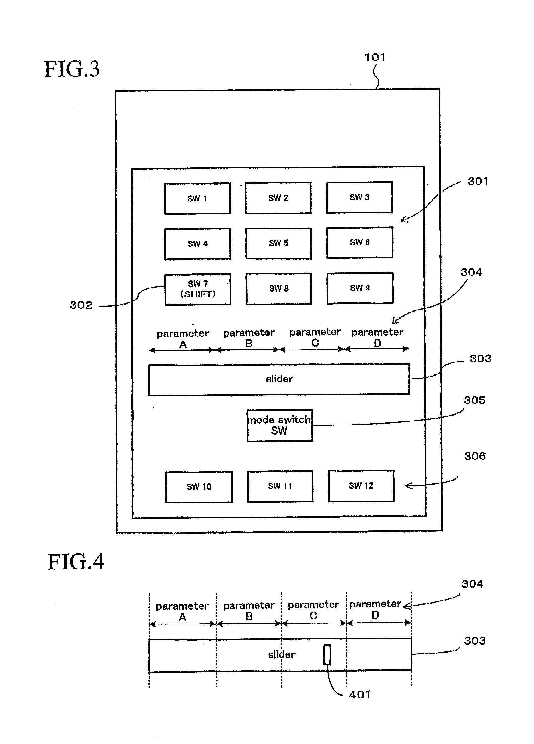
[0022]An embodiment of the present invention will now be described with reference to the drawings. FIG. 1 indicates an example system to which a controller 101 which is an embodiment of the present invention is applied.

[0023]A PC 102 is a general-purpose personal computer; on which integrated music software referred to as a DAW (digital audio workstation) operates. To the PC 102, a general-purpose keyboard and a general-purpose mouse can be connected in order to manipulate the DAW with the keyboard and mouse. By executing the DAW, the PC 102 serves as a music apparatus which realizes various kinds of capabilities for creating music (for example, hard disk recording capability, capability of creating / editing MIDI data and audio data, mixing capability, sequencing capability, etc.).

[0024]To the PC 102, an electronic musical instrument 103, a digital mixer 104, and a speaker 105 are connected. For instance, audio signals output from the electronic musical instrument 103 or the digital ...


PUM


Abstract

A parameter controlling apparatus has a CPU 201 and operation input portion 302, 303 and 305 which include an operating area 303 whose operated position can be detected, and accept input operation. The CPU 201 detects whether the operation input portion is operated in the first manner or the second manner in accordance with the accepted input operation, and detects the content of the input operation of the operating area 303. In a case where the first manner has been detected, the CPU 201 also changes a value of a target parameter in accordance with the content of the input operation of the operating area 303. In a case where the second manner has been detected, the CPU 201 also switches a type of a target parameter in accordance with the content of the input operation of the operating area 303.

Description

BACKGROUND OF THE INVENTION[0001]1. Field of the Invention[0002]The present invention relates to a parameter controlling apparatus for changing a value of a parameter assigned to an operating element as a target which is to be controlled by use of the operating element, and more particularly to an art for switching a target parameter which is to be assigned to the operating element.[0003]2. Description of the Related Art[0004]Conventionally, there is a touch type (slider type) operating element which allows a user to change the value of a target parameter with the touch of the operating element. The touch type operating element is widely used as a means of assigning one of various kinds of parameters as a target parameter such as a parameter for setting a level of acoustical signal, and changing a value of the assigned parameter. Various kinds of music apparatuses have quite a large number of types of parameters which are to be specified. In some cases, however, due to limitation of...

Claims


Application Information

Patent Timeline
IPC IPC(8): H02B1/00
CPCG06F3/0488G06F3/04847
Inventor KAMIHARA, MASANORIKITAYAMA, TORU
Owner YAMAHA CORP
Why Eureka
Try Eureka