Windshield wiper device

a wiper device and windshield wiper technology, applied in vehicle maintenance, roof cleaning, vehicle maintenance, etc., can solve the problems of increasing assembly costs, requiring a large amount of time for riveting or screwing, etc., and achieve the effect of holding the rubber part especially reliably

Inactive Publication Date: 2009-11-17
ROBERT BOSCH GMBH
View PDF35 Cites 1 Cited by
  • Summary
  • Abstract
  • Description
  • Claims
  • Application Information

AI Technical Summary

Benefits of technology

[0003]The aim of the invention is improving the windshield wiper device of the type cited at the outset such that in the future it can be mounted on the vehicle body more quickly and therefore more cost-effectively.
[0025]If the rubber part can be positioned on at least one pin before final mounting of the molded tube, the assembly personnel is able to mount the molded tubes that are delivered in this state on the vehicle body more quickly.

Problems solved by technology

In addition, screwing or riveting requires a relatively great amount of time, which increases assembly costs.

Method used


Image

  • Windshield wiper device
  • Windshield wiper device
  • Windshield wiper device

Examples


Embodiment Construction

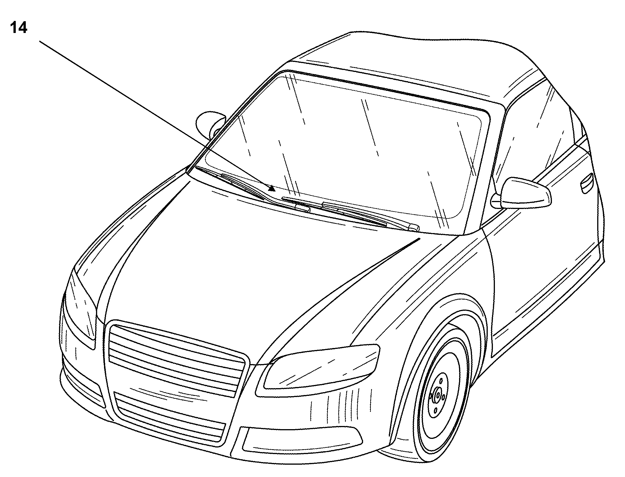
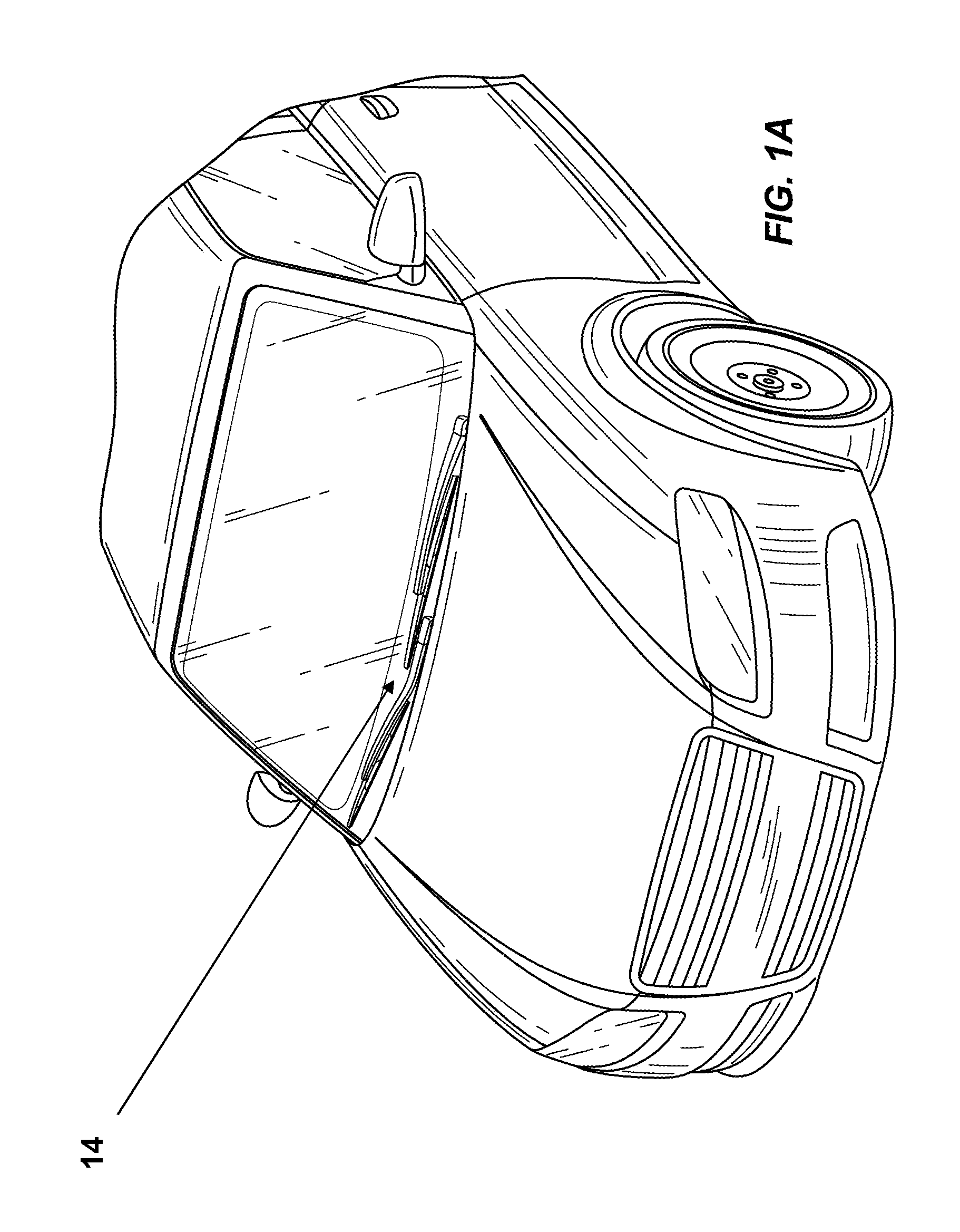
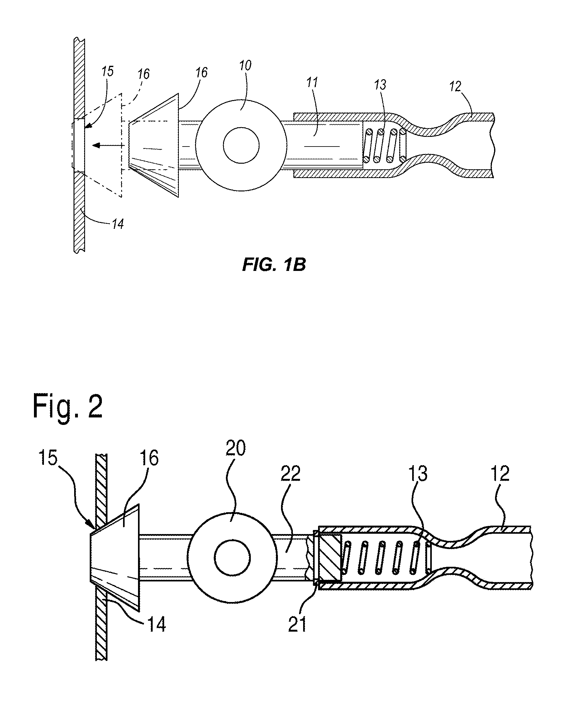
[0044]FIG. 1A shows a motor vehicle including a vehicle body 14 and a windshield wiper device. FIG. 1B shows a portion of the windshield wiper device which can have a molded tube 10 with a projection 11, which is inserted into a tube 12. The molded tube 10 and the projection 11 can be displaced in the tube 12 relative to it. A spring 13 is arranged on the end of the projection 11, and this spring moves (as indicated by the arrow) the molded tube 10 towards an opening 15 provided in a vehicle body 14.

[0045]A fastening point 16, which can be inserted into the opening 15 (as shown in phantom in FIG. 1B), is provided on the molded tube 10. Because of the spring 13, the molded tube 10 can be mounted quickly and simply. In addition, the spring 13 presses the molded tube 10 reliably against the vehicle body 14 even in the case of shocks.

[0046]In addition to the spring 13, a molded tube 20 can be provided with a securing ring 21 (see FIG. 2), which locks the molded tube 20 when the fastenin...


PUM


Abstract

A windshield wiper device with fastening points (16), by means of which the windshield wiper device is fastened to a body (14) of a motor vehicle. Until now windshield wiper systems were screwed or riveted to the vehicle body so that special tools and a relatively great amount of time are required. The aim of the invention is improving the windshield wiper device so that it can be mounted on the vehicle body more quickly and therefore more cost-effectively. As a result, according to the invention, at least one of the fastening points (16) can move towards the vehicle body (14) for mounting the windshield wiper device.

Description

BACKGROUND OF THE INVENTION[0001]The invention relates to a windshield wiper device with fastening points, by means of which the windshield wiper device is fastened to a body of a motor vehicle.SUMMARY OF THE INVENTION[0002]Until now windshield wiper systems were screwed or riveted to the vehicle body. Special tools were required for screwing or riveting. In addition, screwing or riveting requires a relatively great amount of time, which increases assembly costs.[0003]The aim of the invention is improving the windshield wiper device of the type cited at the outset such that in the future it can be mounted on the vehicle body more quickly and therefore more cost-effectively.[0004]The invention attains the stated aim with a windshield wiper device of the type cited at the outset wherein, according to the invention, at least one of the fastening points can move towards the vehicle body for mounting the windshield wiper device. In this way, the windshield wiper device can be clamped bet...

Claims


Application Information

Patent Timeline
Patent Type & Authority Patents(United States)
IPC IPC(8): B60J1/02
CPCB60S1/0422B60S1/0469B60S1/0447B60S1/0488B60S1/04
Inventor ZIMMER, JOACHIMALBRECHT, GERARDRAPP, JUERGENSCHABANEL, FRANCOISBOOS, TINOESCHENBRENNER, NICOLASPORCHET, FRANK
Owner ROBERT BOSCH GMBH
Why Eureka
Try Eureka