Heat dissipation device
a heat dissipation device and heat dissipation technology, which is applied in the direction of positive displacement liquid engines, lighting and heating apparatus, liquid fuel engines, etc., can solve the problems of poor heat dissipation efficiency, and large noise, so as to reduce the power consumption of the heat dissipation device in operation, the portability electronic device becomes much thinner, and the noise generated by the conventional fan is eliminated.
- Summary
- Abstract
- Description
- Claims
- Application Information
AI Technical Summary
Benefits of technology
Problems solved by technology
Method used
Image
Examples
first embodiment
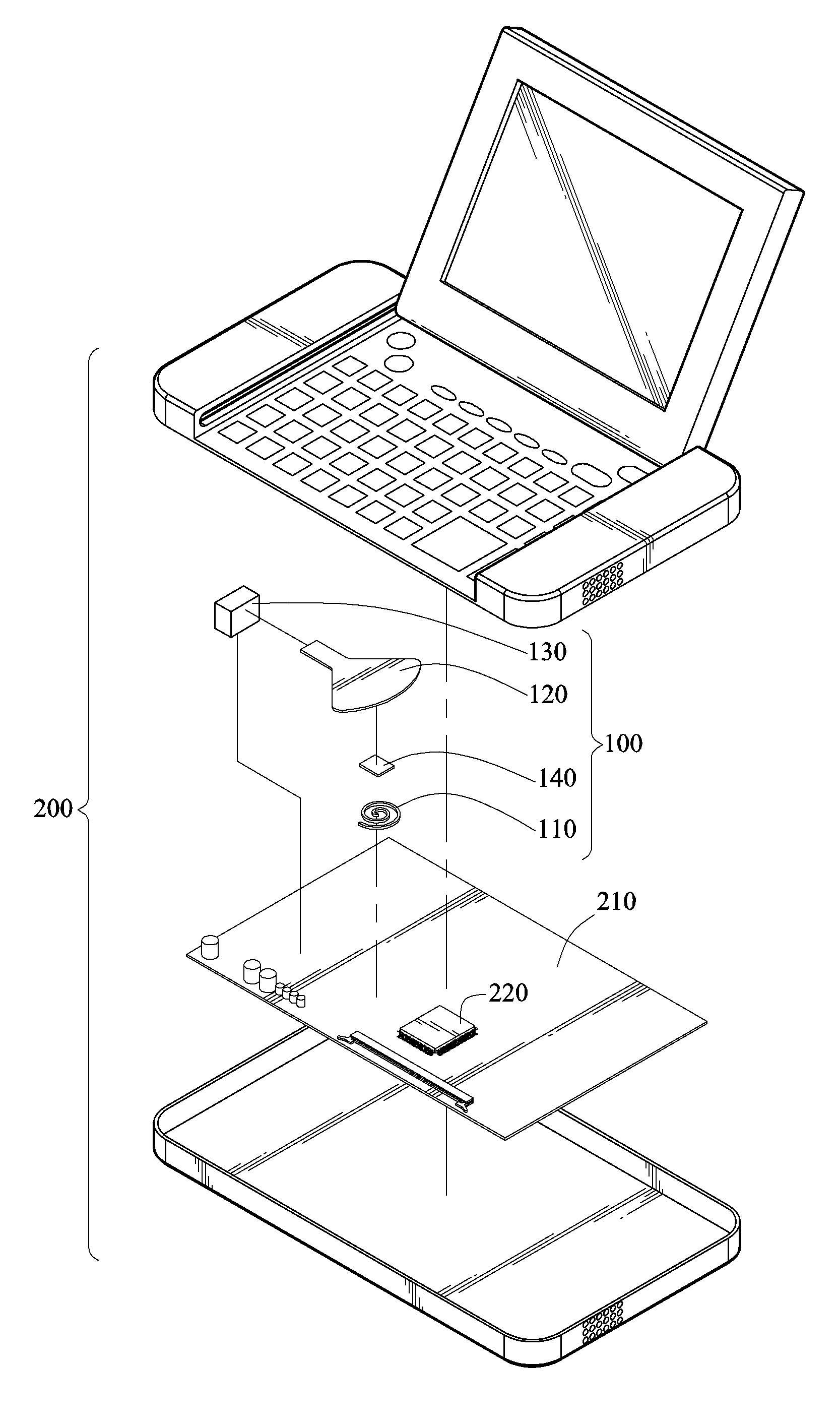
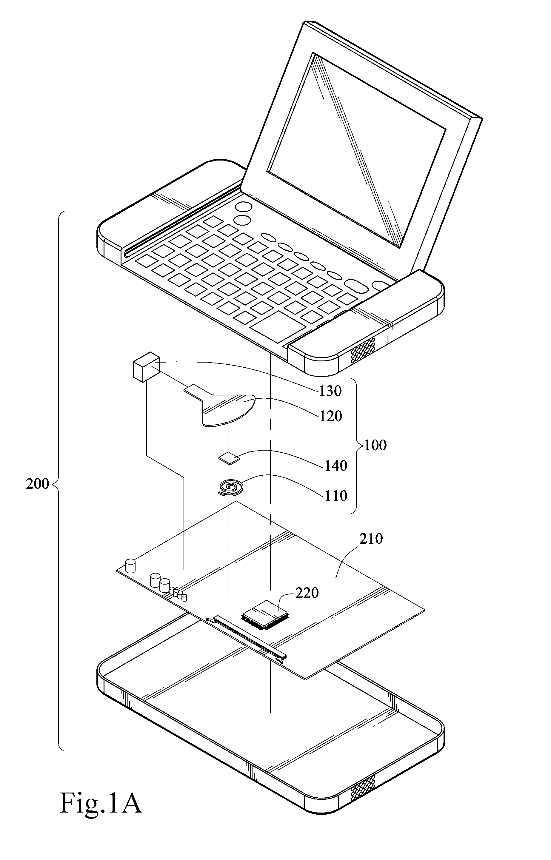
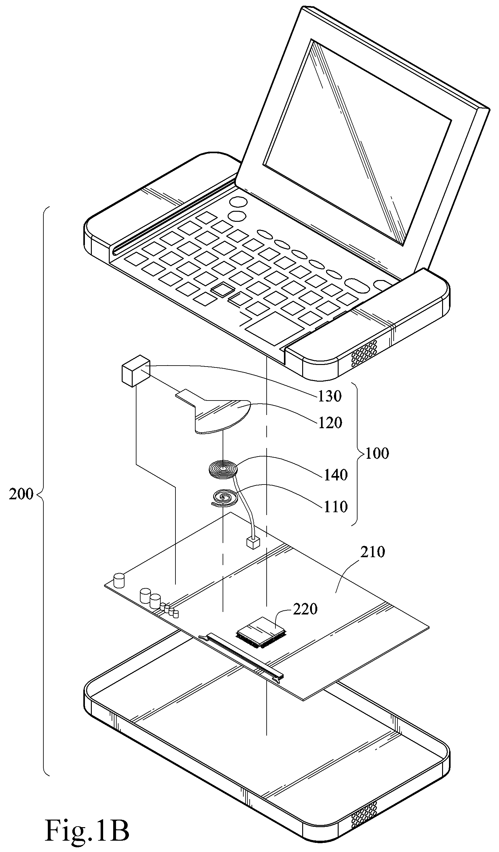
[0026]Please refer to the exploded views of FIGS. 1A and 1B, a heat dissipation device 100 according to the present invention is disposed inside an electronic device 200, and electrically connected to a intermittent power source, for dissipating the heat generated by at least one heat-generating element 220 (at least one electronic component) on a circuit board 210. The intermittent power source may be a direct current (DC) power source having a plurality of consecutive power intervals and no-power interval, or an alternating current (AC) power source with a fixed current period, such as a sinusoidal wave power source. The aforementioned intermittence may be a fixed period or a variable period, and may also be a pulse width modulation (PWM) signal. The clock lengths of the power intervals and no-power intervals of the intermittent power source, or the time durations of the positive, negative semi-cycles of the AC power source are controlled by a basic input / output system (BIOS), suc...
second embodiment
[0034]FIGS. 3A and 3B are side views of the present invention. The vibrating sheet 120 of the present invention may be a ferromagnetic sheet with magnetic permeance, such that the vibrating sheet 120 has the material characteristics of magnetic permeance and elastic deformation. The vibrating sheet 120 is suspended above over the coil 110, and interacts with the magnetic field produced by the coil 110. Therefore, the movable portion 122 of the vibrating sheet 120 flutters up and down under the magnetic force of the magnetic field, so as to produce an airflow for dissipating the heat produced by the heat-generating element 220.
third embodiment
[0035]FIGS. 4A and 4B are side views of the present invention. A block of ferromagnetic material 150 is covered on a portion of the surface of the movable portion 122, such that the movable portion 122 suspended over the coil 110 flutters up and down under the action of magnetic force of the magnetic field, so as to produce an airflow for dissipating the heat produced by the heat-generating element 220.
[0036]Referring to FIGS. 5A to 5C, side views of wiggling leaves of different configurations are shown. The vibrating sheet 120 of the present invention further includes a flexible portion 123 jointed between an end surface of the fixed portion 121 and an end surface of the movable portion 122 opposite to the end surface of the fixed portion 121. The vibrating sheet 120 having the fixed portion 121, the movable portion 122, and the flexible portion 123 may be formed monolingual. Or, the material of the flexible portion 123 may be different from that of the fixed portion 121 and the mo...
PUM
 Abstract
Description
Claims
Application Information
 - R&D
- Intellectual Property
- Life Sciences
- Materials
- Tech Scout
- Unparalleled Data Quality
- Higher Quality Content
- 60% Fewer Hallucinations
Browse by: Latest US Patents, China's latest patents, Technical Efficacy Thesaurus, Application Domain, Technology Topic, Popular Technical Reports.
© 2025 PatSnap. All rights reserved.Legal|Privacy policy|Modern Slavery Act Transparency Statement|Sitemap|About US| Contact US: help@patsnap.com


