Method and apparatus for controlling the tip speed of a blade of a wind turbine

a wind turbine and tip speed technology, applied in the direction of electric generator control, rotors, vessel construction, etc., can solve the problem of limiting the noise generation of wind turbines, and achieve the effect of minimizing the amount of noise generated, and reducing the noise generation of wind turbines

Inactive Publication Date: 2010-07-27
GENERAL ELECTRIC CO
View PDF15 Cites 33 Cited by
  • Summary
  • Abstract
  • Description
  • Claims
  • Application Information

AI Technical Summary

Benefits of technology

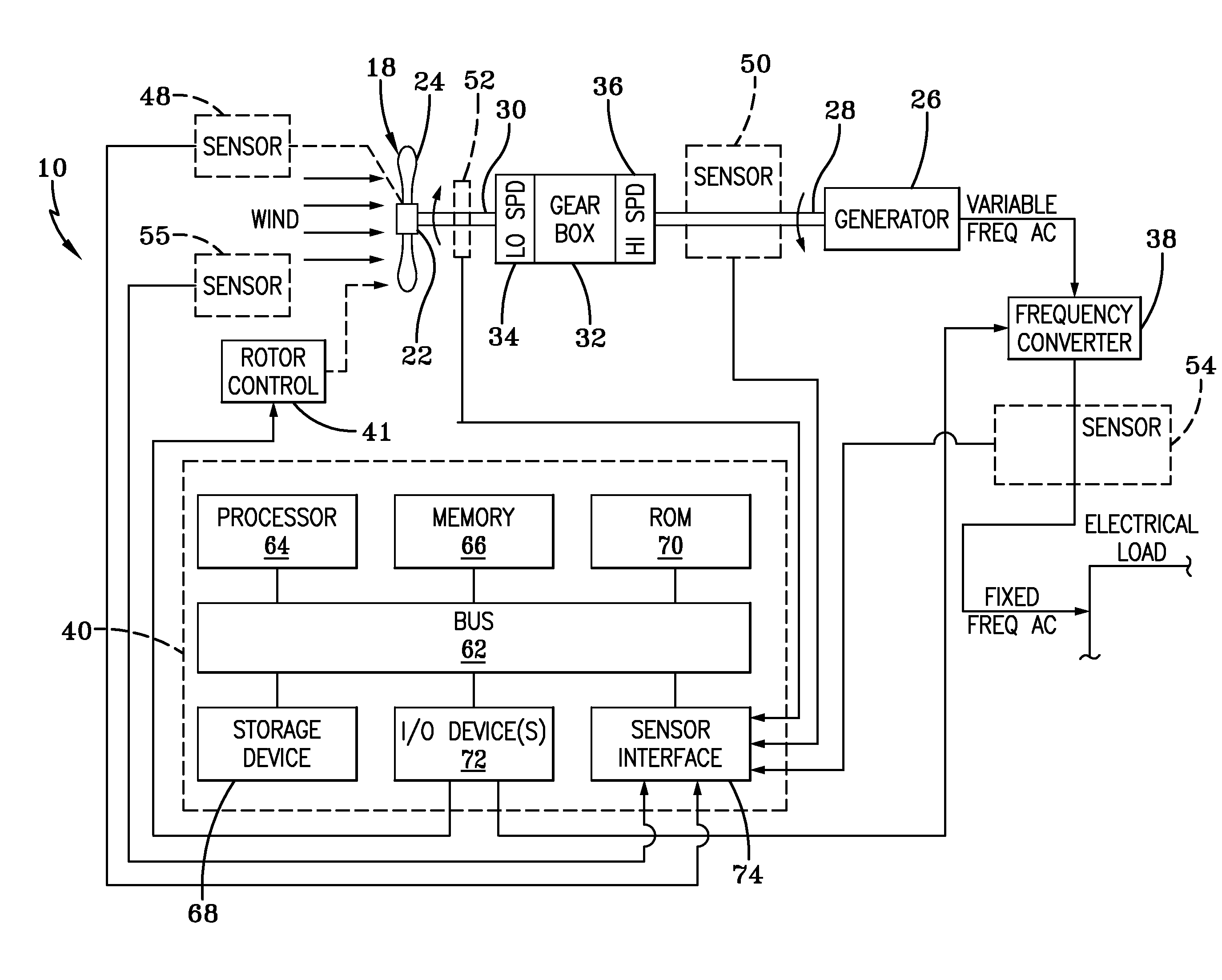
[0008]The system described herein has many advantages, including, but not limited to, the ability to meet specific maximum noise levels with minimal loss in annual energy yield. The system monitors the wind speed or other parameters and adjusts the maximum tip speed of the wind turbine blade accordingly. For lower wind speeds, the maximum tip speed is limited to minimize the amount of noise generated by the rotation of the blades. However, for higher wind speeds there is no need to limit the maximum tip speed of the blade, as the background noise of the wind (i.e., the ambient or background sounds of the wind itself in the areas surrounding the wind turbine) will cover even a larger noise generation of the wind turbine. In addition, the movement of the blade pitch towards feather during increased wind speeds limits the wind turbine noise generation. Hence, as the tip speed limit is not required for all wind speeds, the turbine can be re-accelerated and the original rated power achieved without causing the noise level of the wind turbine to increase beyond the background noise generated by the wind.

Problems solved by technology

In addition, the movement of the blade pitch towards feather during increased wind speeds limits the wind turbine noise generation.

Method used


Image

  • Method and apparatus for controlling the tip speed of a blade of a wind turbine
  • Method and apparatus for controlling the tip speed of a blade of a wind turbine
  • Method and apparatus for controlling the tip speed of a blade of a wind turbine

Examples


Embodiment Construction

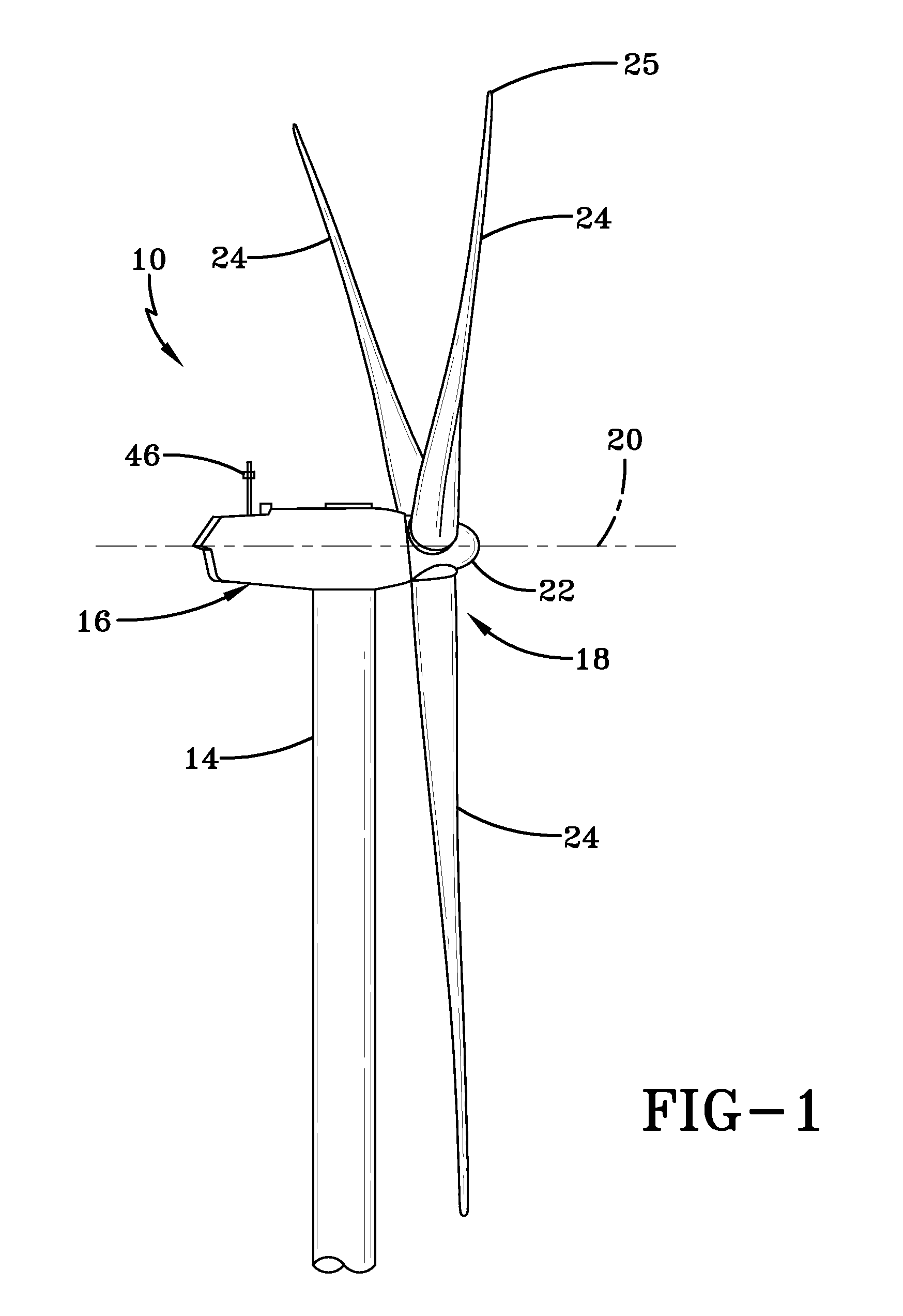
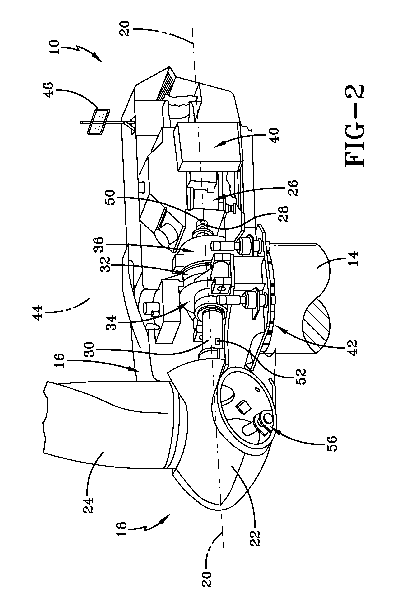
[0018]As used herein, the term “blade” is intended to be representative of any device that provides reactive force when in motion relative to a surrounding fluid. As used herein, the term “wind turbine” is intended to be representative of any device that generates rotational energy from wind energy, and more specifically, converts kinetic energy of wind into mechanical energy. As used herein, the term “wind generator” is intended to be representative of any wind turbine that generates electrical power from rotational energy generated from wind energy, and more specifically, converts mechanical energy converted from kinetic energy of wind to electrical power. As used herein, the term “windmill” is intended to be representative of any wind turbine that uses rotational energy generated from wind energy, and more specifically, mechanical energy converted from kinetic energy of wind, for a predetermined purpose other than generating electrical power, such as, but not limited to, pumping ...


PUM


Abstract

A method for controlling a tip speed of a blade of a wind turbine. The method includes determining the wind speed proximate the wind turbine; maintaining a first substantially constant rotational speed of the tip of the blade during variable wind speeds above a first predetermined nominal wind speed and below the second predetermined nominal wind speed; maintaining a second substantially constant rotational speed of the tip of the blade during variable wind speeds above a second predetermined nominal wind speed. The noise generated by wind at the second predetermined nominal wind speed is greater than noise generated by the blade at the second constant rotational speed of the tip of the blade.

Description

FIELD[0001]The present disclosure is directed to a system for controlling the operation of a wind turbine, and specifically to a system which meets specific noise levels with minimal loss in energy yield.BACKGROUND[0002]Wind energy systems have gained more and more importance as a source of energy in recent years. As areas suitable for their economical operation are relatively scarce in a number of countries, a growing number of wind energy systems are located close to populated areas. As the running of wind turbines in wind energy systems causes noise, this leads to various problems, such as resistance from neighborhoods and the like. A variety of factors contribute to the overall noise emission of such systems, such as tonal noise emissions and aerodynamic noise emissions.[0003]Methods for reducing the noise emissions of wind energy systems have long been discussed. For example, it has been proposed to reduce aerodynamic noise caused by the blades through a speed / torque control of...

Claims


Application Information

Patent Timeline
Patent Type & Authority Patents(United States)
IPC IPC(8): H02P9/04F03D9/00
CPCF03D7/0224F03D7/0276F03D7/043F05B2260/80F05B2260/96F05B2270/304F05B2270/32F05B2270/327F05B2270/328F05B2270/333F05B2270/335Y02E10/721Y02E10/723Y02E10/726Y02P80/30Y02E10/72
Inventor KINZIE, KEVINHERR, STEFANPETITJEAN, BENOIT
Owner GENERAL ELECTRIC CO
Why Eureka
Try Eureka