Line runner for conduit

a line runner and conduit technology, applied in the direction of cables, slitting machines, transportation and packaging, etc., can solve the problems of limiting the flexibility of the conduit, the relative complexity of the two pieces, and the cost of the runner,

Inactive Publication Date: 2009-11-24
HAMRICK JAMES C
View PDF23 Cites 17 Cited by
  • Summary
  • Abstract
  • Description
  • Claims
  • Application Information

AI Technical Summary

Benefits of technology

[0009]The line runner of my invention may be used in conduit of the same inflated diameter or in conduit of smaller diameter thus eliminating the need for multiple size runners and also accommodating changes in diameter of the conduit. By providing three different bag or sleeve diameters most of the commercially installed conduit can be accommodated. In the larger diameter bags or sleeves it is desirable to diagonally heat seal the corners of the leading or front side of the bag as it has been discovered that such corner sealing promotes the inflation of the larger bags.

Problems solved by technology

This device has the disadvantage of being relatively complex comprising two pieces which add to its cost and limits its flexibility within conduit.
The diameter of the torpedo has to match rather closely the inner diameter of the conduit as the torpedo is rigid or semi-rigid and appears to be relatively costly to make.
The foregoing patents are exemplary of prior art devices which employ rigid or semi-rigid or inflexible line-pullers or torpedoes and are relatively costly.

Method used


Image

  • Line runner for conduit
  • Line runner for conduit
  • Line runner for conduit

Examples


Embodiment Construction

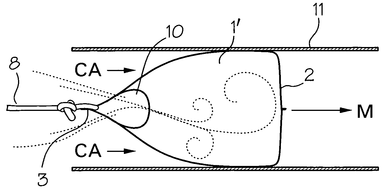
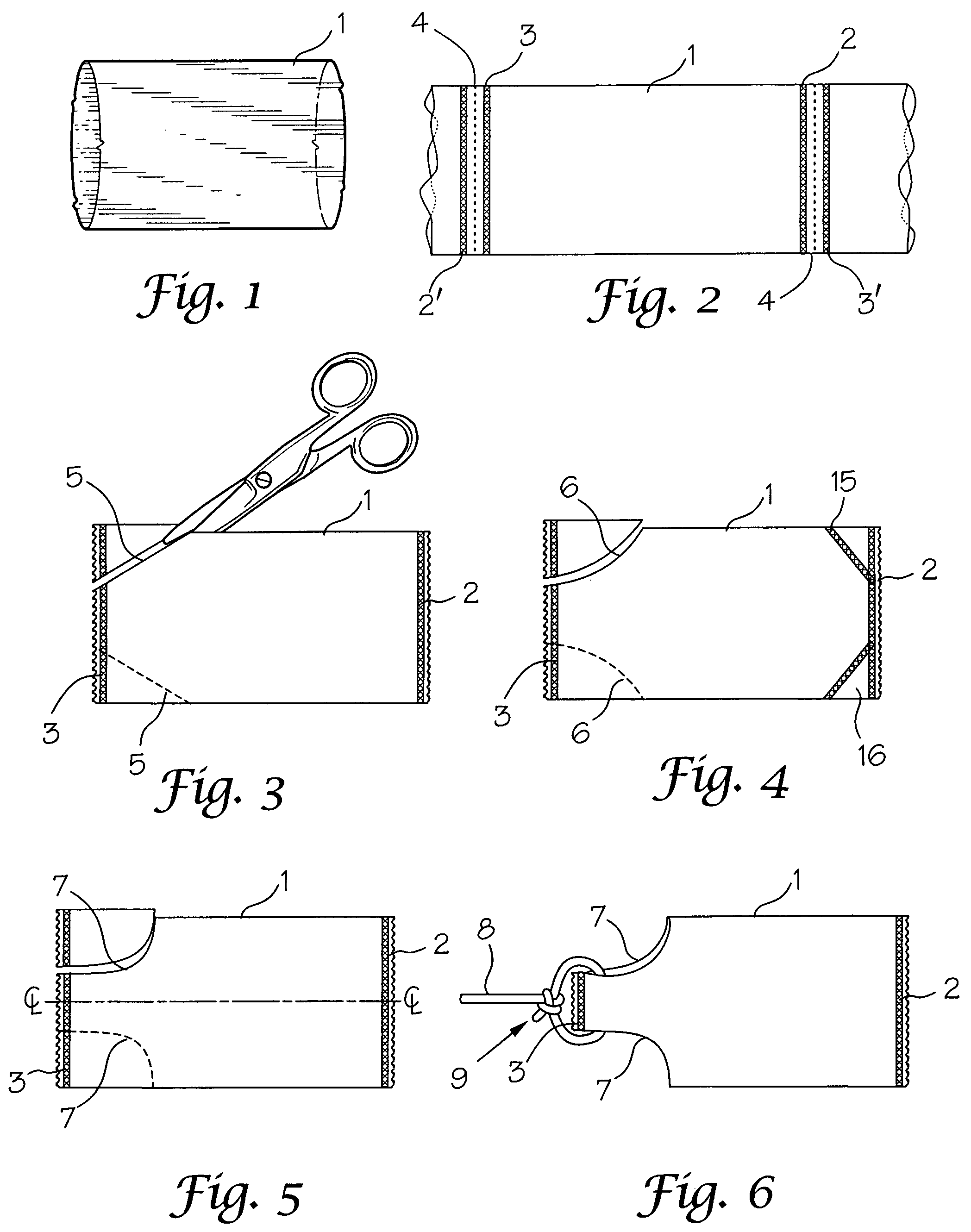
[0022]Turning first to FIG. 1, tubular sleeve 1 is shown. Preferably this is a seamless tube of a thermoplastic material such as linear low-density polyethylene which is a very tough and strong form of polyethylene. Other heat sealable polymeric materials may also be used such as polypropylene, polyesters and nylon. While the seamless tube is preferred as the starting point for making the line runner of the present invention, superimposed sheets of heat sealable material may be longitudinally side sealed to form a tube also. Gussets may also be formed by inwardly creasing of both sides of the tube before sealing in the lay flat condition. FIG. 2 shows the tube or sleeve of FIG. 1 in lay flat condition where the sleeve 1 is heat-sealed at spaced apart intervals with transverse heat seals 2 and 3 which form the respective front and rear seals of the bag and along cut lines or score lines 4. The bags are preferably severed one from the other by a heat sealing process that in one seal a...


PUM


Abstract

A carrier for pulling line through conduit, the carrier or line runner being an inflatable plastic sleeve that is closed at one end with gusset openings at the other end through which a line may pass and be tied to itself so that when the line runner is placed in a conduit with its closed end in the direction of travel, the application of lower pressure at the closed end will cause the sleeve to inflate and be propelled in the direction of the lower pressure pulling the line with it.

Description

FIELD OF THE INVENTION[0001]This invention relates to a flexible line runner for installing line in conduit, particularly in conduit having bends and differing diameters.BACKGROUND OF THE INVENTION[0002]Conduit is installed in a wide variety of construction projects ranging from residential and commercial buildings to transmission from central, electrical and communication distribution stations. After installation, the desired line must be run through the conduit. One common approach is to attach lightweight rope or cord onto a projectile which is inserted in one end of the conduit and driven through the conduit by air. The projectiles have taken several forms such as that of the drogue described in U.S. Pat. No. 6,932,323 to Benjamin James on Aug. 23, 2005 entitled “Drogue Having Based End Opening” where a flexible bag having an end opening allowing the bag to be inflated and pneumatically propelled along conduit, the bag bearing attached to and driving a biasing member which resil...

Claims


Application Information

Patent Timeline
Patent Type & Authority Patents(United States)
IPC IPC(8): H02G1/08
CPCH02G1/086
Inventor HAMRICK, JAMES C.
Owner HAMRICK JAMES C
Why Eureka
Try Eureka