Apparatus for and method of determining distance

a technology of determining distance and apparatus, which is applied in the direction of distance measurement, instruments, surveying and navigation, etc., can solve the problems of increasing distance, increasing the signal-to-noise ratio of determining distance, and increasing the distance, so as to improve the determination of distance, save energy, and reduce errors

Active Publication Date: 2009-11-24
IRIS
View PDF10 Cites 17 Cited by
  • Summary
  • Abstract
  • Description
  • Claims
  • Application Information

AI Technical Summary

Benefits of technology

[0017]The invention enjoys the advantage that two integrators which are actuable independently of each other are provided for detection of a reflected light pulse so that the integrators can be started in particular in time succession whereby in total a greater proportion of the reflected light pulse is incident in the cumulated integration time of both integrators. It is essential for measuring distance that each integrator has an integration time which at a maximum corresponds to the pulse duration of the light pulse so that, with one integrator, necessarily only a leading or a trailing portion of the reflected light pulse can be detected in order to acquire distance information. In a corresponding fashion, with one integrator, only a part of the energy of the reflected light pulse can be detected. Two integrators involving different integration times which both respectively involve at a maximum the pulse duration of the reflected light pulse (which spreads due to phase delays as a consequence of dispersion and can therefore be longer than the emitted light pulse) can in combination acquire the total energy of the reflected light pulse. With a short distance and a correspondingly short transit time in respect of the reflected light pulse the integrator which is started first acquires a greater part of the energy while, with a longer transit time in respect of the light pulse, the integrator which started later and which concludes integration later acquires a greater part of the energy of the reflected light pulse. That enhances the accuracy of distance measurement in a double sense: measurement errors are averaged out and the potentially very small number of photons detected is put to optimum use.
[0065]As the quality of determining distance decreases with increasing distances by virtue of the intensity, which decreases quadratically, of the reflected components of the emitted light pulse, a preferred variant of the method provides that in the first measurement cycle in the step of emitting the light pulse a light pulse of a first pulse duration and a first intensity is emitted and in the second measurement cycle in the step of emitting the light pulse a light pulse of a second pulse duration and a second intensity is emitted, wherein the first pulse duration is greater than the second pulse duration and the first intensity is lower than the second intensity. The greater second intensity causes a correspondingly increased intensity in respect of the reflected components of the emitted light pulse so that the distance determining procedure which is performed in the second measurement cycle, for great distances, is improved in respect of the measurement result.

Problems solved by technology

All known methods of determining distance by measurement of the transit time of a light pulse suffer from the disadvantage that the intensity of the reflected components of the emitted light pulse decreases in square relationship with the distance to the reflecting object.
As a result the signal-noise ratio in respect of determining distance worsens with increasing distance to the reflecting object.
A further disadvantage of the known distance measurement methods is that in principle only a part of the reflected light pulse is integrated for distance determination purposes, the magnitude of the integrated component being dependent on the transit time of the light pulse.
That means that the signal-to-noise ratio additionally worsens for the measurement procedure because a smaller integrated useful signal is confronted with a constant noise signal.

Method used


Image

  • Apparatus for and method of determining distance
  • Apparatus for and method of determining distance
  • Apparatus for and method of determining distance

Examples


Embodiment Construction

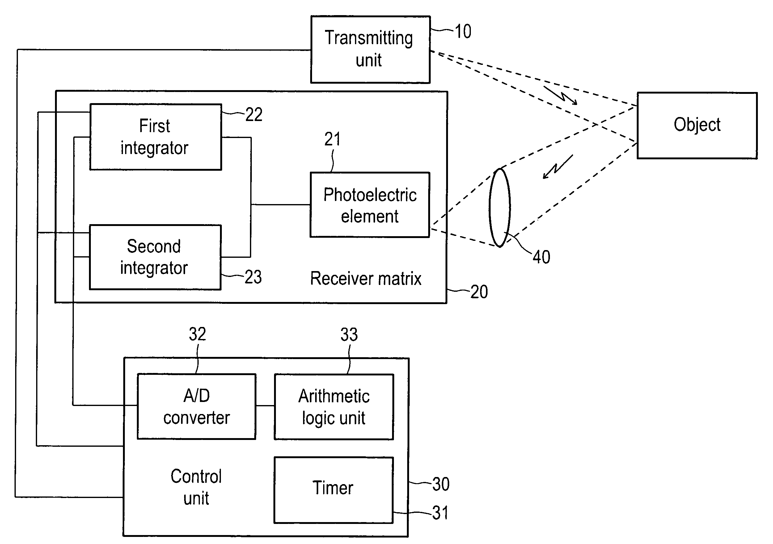
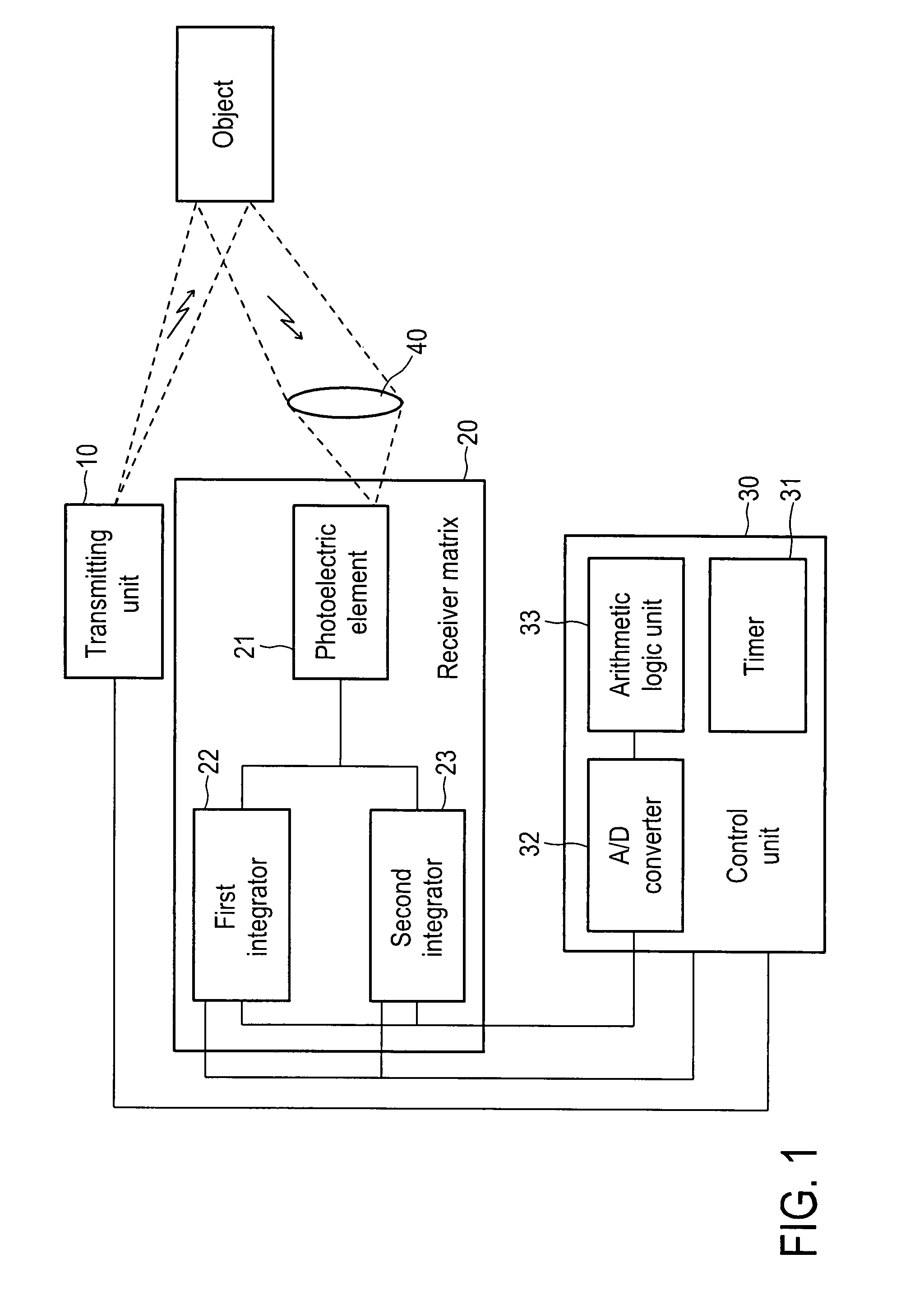
[0077]FIG. 1 shows a view of an embodiment of the apparatus according to the invention in the form of a block diagram. The distance determining apparatus is divided into three main components, a transmitting unit 10, a receiver matrix 20 and a control unit 30, which are connected together by signal lines. The transmitting unit 10 is adapted to emit a light pulse at the instigation of the control unit 30, the pulse duration and the intensity of the emitted light pulse being predetermined by the control unit 30. The components of the emitted light pulse, which are reflected by an object, go to an optical means 40 which projects the incident reflected components onto a photoelectric element 21 or a two-dimensional array of photoelectric elements 21. The photoelectric element 21 forms part of the receiver matrix 20 which, for each photoelectric element 21, has a first integrator 22 and a second integrator 23, the integrator inputs of which are connected to the output of the photoelectri...


PUM


Abstract

Apparatus for determining distance comprising a transmitting unit for emitting a light pulse, a receiver matrix having at least one photoelectric element and a control unit, wherein the receiver matrix has a first and a second integrator which are connected to the photoelectric element, which are activatable independently of each other and which are each adapted to integrate a measurement signal outputted by photoelectric element over a period of time predetermined by the control unit and thereby to form an integrator state and to output the integrator state as an output signal.

Description

CROSS REFERENCE TO RELATED APPLICATIONS[0001]This application claims priority under 35 USC §119 to German Patent Application No. 10 2006 029 025.9-55 filed on Jun. 14, 2006.BACKGROUND OF THE INVENTION[0002]1. Technical Field[0003]The invention concerns an apparatus for and a method of determining distance. Apparatuses for and methods of determining distance in the sense of the present invention are based on the principle of emitting a light pulse and measuring the transit time between the commencement of emission of the light pulse and the reception of the components of the light pulse, which are reflected by an object. The distance to a reflecting object is afforded in that case in the form of the product of half the measured transit time and the speed of light.[0004]2. Discussion of Related Art[0005]Apparatuses for determining distance which are known in the state of the art have a transmitting unit for emitting a light pulse, a receiver matrix having at least one photoelectric el...

Claims


Application Information

Patent Timeline
Patent Type & Authority Patents(United States)
IPC IPC(8): G01C3/08G01S7/4863G01S7/4865G01S17/894
CPCG01S7/487G01S7/4865G01S17/89G01S7/4863G01S17/894
Inventor THUN, ANDREASWAGNER, WILFRIED
Owner IRIS
Why Eureka
Try Eureka