Interrupt controller

a controller and interrupt technology, applied in the direction of instruments, liquid/fluent solid measurement, sustainable buildings, etc., can solve the problems of ultra low power design and interrupt controller consumption, and achieve the effect of saving power, saving a significant amount of power, and reducing the static power consumption of the interrupt controller

Active Publication Date: 2009-11-24
ARM LTD
View PDF11 Cites 66 Cited by
  • Summary
  • Abstract
  • Description
  • Claims
  • Application Information

AI Technical Summary

Benefits of technology

[0014]In this way, the static power consumption of the interrupt controller can be reduced when the interrupt controller is not required to be fully active by switching unused sections of the interrupt controller into a low power mode. In particular, the interrupt control circuitry, which is powered in the first domain, can be switched into a low power mode, thereby saving power, while incoming interrupt requests can continue to be monitored by interrupt request monitoring circuitry, which is powered in the second domain. The first domain, and thus the interrupt control circuitry, can be switched out of the low power mode if an interrupt request is received which necessitates handling by the interrupt control circuitry. The relatively complex decision making logic of the interrupt controller, which accordingly uses a relatively large amount of power, can be provided in the interrupt control circuitry, thereby saving a significant amount of power when the interrupt control circuitry is switched into the low power mode. In contrast, the complexity of the interrupt request monitoring circuitry can be kept to a relatively low level, thereby resulting in relatively low power usage even though the interrupt request monitoring circuitry is constantly powered in the second domain. It should be noted that by interrupt we mean any “wake up event”, thus as well as conventional interrupts, the interrupt controller is also responsive to resets or other system events such as those required for multi-processor systems.
[0015]The low level of complexity of the interrupt request monitoring circuitry can be achieved at least in part because the decision making process of determining which of the monitored interrupts requests should trigger the first domain can be carried out by the interrupt control circuitry. The resulting selection of interrupt requests can then be communicated to the interrupt request monitoring circuitry in response to a low power request signal prior to the interrupt control circuitry being switched into the low power mode. In this way, all that is in principle required of the interrupt control monitoring circuitry is to compare each received interrupt request with the selected interrupt requests communicated to the interrupt control monitoring circuitry, and in the case of a match to trigger the first domain to be switched out of the low power mode.
[0017]The low power mode of the first domain may be achieved in several ways. In one example, switching into the low power mode comprises inhibiting clock signals within the first domain, a technique known as clock gating. In another example, switching into the low power mode comprises powering down the first domain by terminating, or at least inhibiting, the supply of power to the first domain. The multiple domains may be achieved by providing multiple power islands which can be separately powered up and down. This may increase complexity at implementation time compared with the clock gating methods of reducing power consumption in the domains, but the degree of power reduction possible may be worth the increase in complexity for some low power applications.

Problems solved by technology

The dynamic power consumption of the interrupt controller can in this case be reduced by clock gating when the interrupt controller is not in use, but the static power will still remain due to leakage through the silicon, thereby causing problems for ultra low power designs.

Method used


Image

  • Interrupt controller
  • Interrupt controller
  • Interrupt controller

Examples


Embodiment Construction

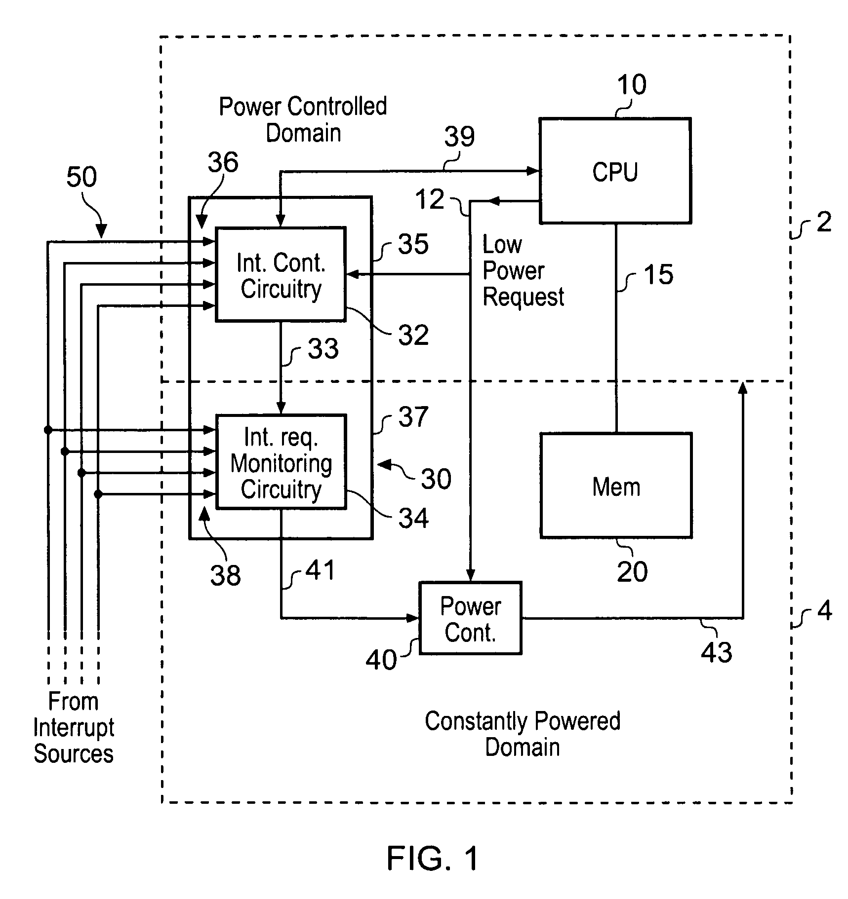
[0036]In FIG. 1, there is schematically illustrated an integrated circuit which is divided into two power domains. In particular, a power controlled domain 2 is provided which can be powered down in order to save power in a low power mode, and a constantly powered domain 4 is provided, which is not powered down in the low power mode. By dividing up the integrated circuit in this way, components of the integrated circuit which can safely be powered down when not required can be provided within the power controlled domain 2, while components which must be constantly powered in order to ensure correct functioning of the integrated circuit can be provided in the constantly powered domain 4.

[0037]In the power controlled domain 2, there is provided a central processing unit 10 for processing instructions and data. The central processing unit 10 can be powered down when no instructions and / or data are pending for processing without losing data or impeding function. Alternatively, the centr...


PUM


Abstract

An interrupt controller for managing interrupt requests comprises interrupt control circuitry in a first domain, the first domain being switchable to a low-power mode, and interrupt request monitoring circuitry in a second domain. The interrupt control circuitry is responsive to a low power request signal received by the interrupt controller to communicate interrupt select information to the interrupt request monitoring circuitry prior to the first domain being switched to a low power mode, the interrupt select information identifying interrupt requests which indicate exit from the low power mode. The interrupt request monitoring circuitry comprises a select information store configured to store the select information communicated to the interrupt request monitoring circuitry by the interrupt control circuitry. The interrupt request monitoring circuitry comprises interrupt inputs for receiving the interrupt requests, and is responsive to a received interrupt request identified by the stored interrupt select information as indicating exit from the low power mode to trigger switching of the first domain out of the low power mode.

Description

BACKGROUND OF THE INVENTION[0001]1. Field of the Invention[0002]This invention relates to an interrupt controller and an interrupt control method. More particularly, embodiments of this invention relate to an interrupt controller and interrupt control method which manage interrupt requests in a low power mode.[0003]2. Description of the Prior Art[0004]In a data processing apparatus, processing logic, for instance a microprocessor, may be responsive to interrupt request signals to interrupt its current operation to service a new operation identified by the interrupt request signals. Handling of these interrupt request signals is usually conducted by an interrupt controller.[0005]For certain applications such as mobile consumer devices, reducing power usage is an important design criterion. In particular, when designing for such applications it is desirable for each component to be configured to save power when not in use. One way of achieving this is to allocate components of a data ...

Claims


Application Information

Patent Timeline
Patent Type & Authority Patents(United States)
IPC IPC(8): G06F13/00
CPCG06F1/3203G06F1/3287Y02B60/1278Y02B60/1282Y02D10/00
Inventor AXFORD, SIMONCRASKE, SIMON JOHN
Owner ARM LTD
Why Eureka
Try Eureka