
Container for gas storage tanks in a vehicle

a technology for gas storage tanks and vehicles, which is applied in the direction of containers, transportation and packaging, electrochemical generators, etc., can solve the problems of not being able to provide protection for high pressure cylindrical storage tanks, vehicles and undercarriages are not configured to achieve the effect of providing maximum available space for fuel storage and facilitating gas removal

Active Publication Date: 2009-12-01
GM GLOBAL TECH OPERATIONS LLC +1
View PDF13 Cites 49 Cited by
  • Summary
  • Abstract
  • Description
  • Claims
  • Application Information

AI Technical Summary

Benefits of technology

[0005]A fuel storage system according to the principles of the present invention includes a container that can be incorporated into a vehicle and installed below the undercarriage of the vehicle or in another suitable location. The container is configured to maximize the available space for storing fuel on a vehicle and includes space for a flow control device to be contained within the container. The container also incorporates ventilation and drainage openings to facilitate the removal of gas and liquids from within the container.

Problems solved by technology

Today's vehicles are not designed for mounting a high pressure storage tank thereon.
With the ability of the liquid fuel storage tanks to be shaped to conform to the configuration of the undercarriage, the undercarriages have not been designed for efficient or optimal use of high pressure cylindrical storage tanks.
Additionally, the vehicles and the undercarriage are not configured to provide the high pressure storage tanks protection from the hazards of driving and in the event of a collision.

Method used


Image

  • Container for gas storage tanks in a vehicle
  • Container for gas storage tanks in a vehicle
  • Container for gas storage tanks in a vehicle

Examples


case 40

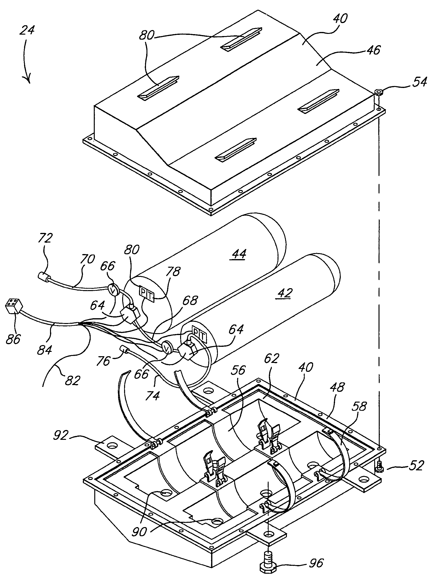
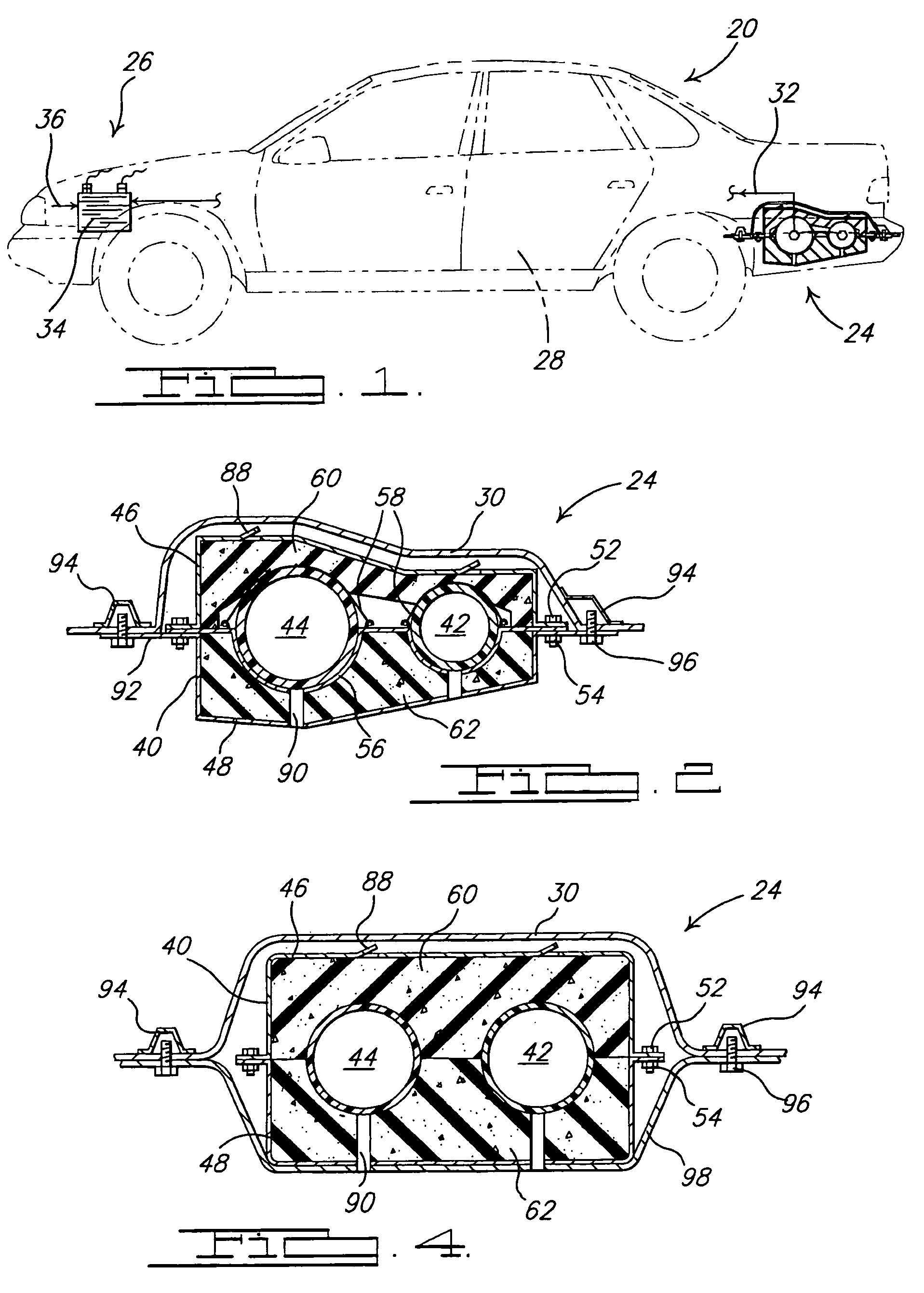
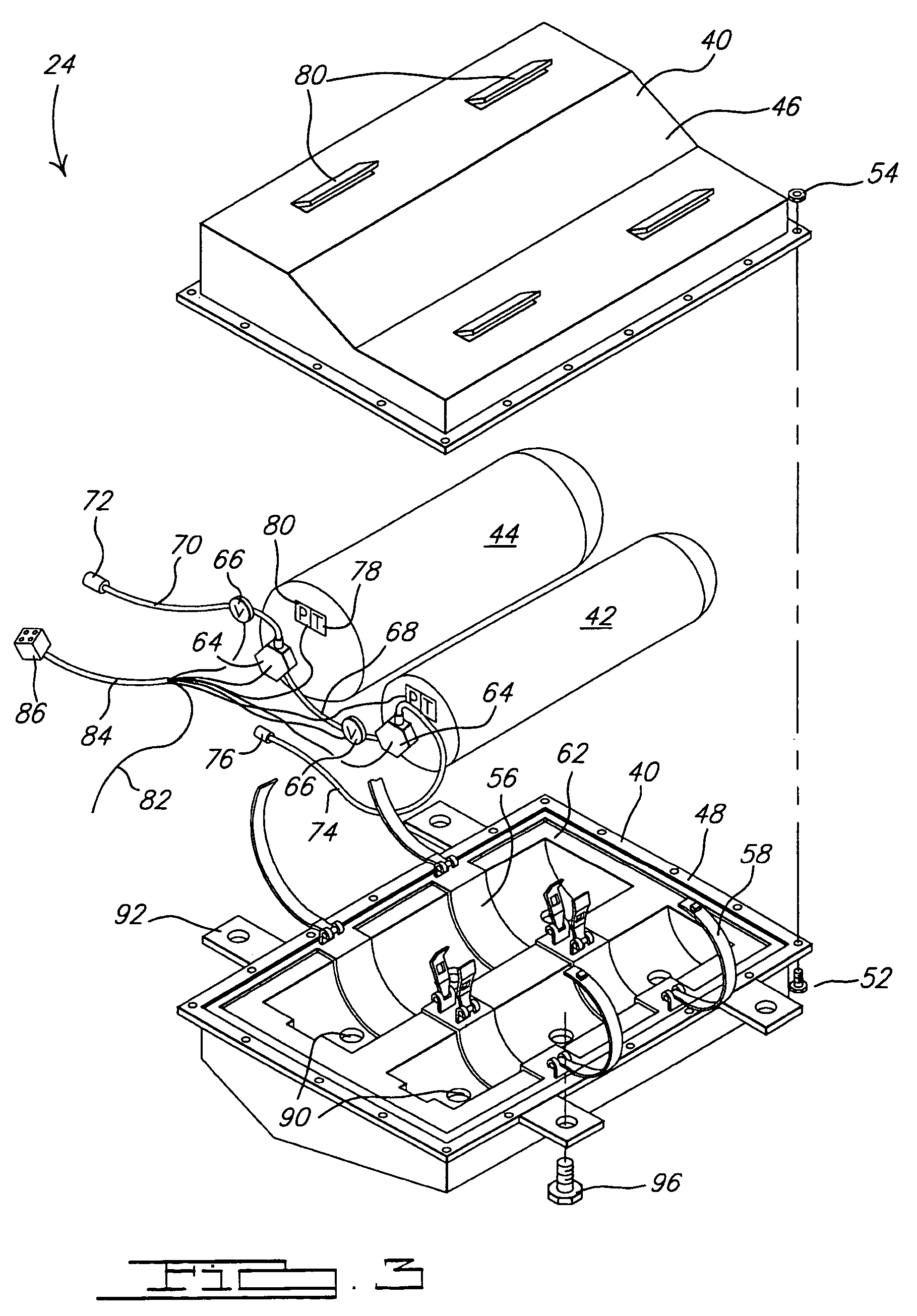
[0021]Case 40 is comprised of a first or upper portion 46 that is configured to surround a portion of storage tanks 42, 44 and a second or lower portion 48 that is configured to surround the remaining portion of storage tanks 42, 44. Upper and lower portions 46 and 48 are attached together to form case 40 which protect storage tanks 42, 44. Upper and lower portions 46 and 48 can be attached together in a variety of ways. For example, as shown in FIGS. 2 and 3, bolts 52 and complementary nuts 54 are used to secure upper and lower portions 46 and 48 together. Alternately, screws, clamps, hinges or other mechanical type fasteners can be used. Upper and lower portions 46 and 48 do not need to be attached together in a fluid tight manner as case 40 is not meant to act as a secondary containment for the fuel in tanks 42, 44.

[0022]The external shape of upper and lower portions 46 and 48 can vary to accommodate the location on vehicle 20 within which fuel storage system 24 is located. That ...


PUM


Abstract

A container for gas storage tanks in a vehicle is disclosed as part of a fuel storage system. The container is dimensioned to include one or more storage tanks along with a flow control device, such as a pressure regulator or automatic valve. The container does not form a fluid-tight containment around the storage tank and includes one or more ventilation openings to allow a gas within the container to be vented therefrom. There is also one or more drain openings in the container to allow liquid within the container to be drained therefrom.

Description

FIELD OF THE INVENTION[0001]The present invention relates to gas storage tanks and, more specifically, to pressurized gas storage tanks in a fuel cell driven vehicle.BACKGROUND OF THE INVENTION[0002]With the changing emissions requirements for vehicles (e.g., automobiles, buses, trucks, etc.) alternative drives (e.g., fuel cell systems) and / or fuels (e.g., hydrogen, liquid natural gas, propane, etc.) are being implemented on the vehicles. To provide efficient storage of these alternate fuels, the fuels are stored at elevated pressures to densify the gas and provide more of the gas in a given volume of space. To facilitate the storing of these gases at higher elevated pressures, cylindrical or cylindrical-like storage tanks are typically employed.[0003]Today's vehicles are not designed for mounting a high pressure storage tank thereon. That is, today's vehicles typically store their liquid fuel in a zero pressure or slightly pressurized storage tank that is positioned adjacent the un...

Claims


Application Information

Patent Timeline
Patent Type & Authority Patents(United States)
IPC IPC(8): F17D1/00
CPCB60K15/03006B60K15/07F17C13/083B60K15/063F17C2270/0184B60K2015/03118B60K2015/03164B60K2015/0638Y02E60/321Y02E60/34F17C2205/0192F17C2201/0109F17C2201/035F17C2201/056F17C2205/0115F17C2205/013F17C2205/0326F17C2221/012F17C2221/033F17C2221/035F17C2223/0123F17C2223/0153F17C2223/033F17C2223/036F17C2250/036F17C2250/0447F17C2260/038F17C2265/04F17C2270/0171F17C2270/0176F17C2270/0178Y02E60/32Y10T137/474Y10T137/4857
Inventor SUESS, UWEHILVERT, LUDGER
Owner GM GLOBAL TECH OPERATIONS LLC
Learn More