Bike light

Inactive Publication Date: 2009-12-01
PETERSON GARY
View PDF15 Cites 5 Cited by
  • Summary
  • Abstract
  • Description
  • Claims
  • Application Information

AI Technical Summary

Benefits of technology

[0012]It is an object of the present invention to provide a new and improved light for bikes.
[0013]It is an object of the present invention to provide a new and improved light for bikes that is easy and quickly applied to a bike wheel.
[0014]It is an object of the present invention to provide a new and improved light for bikes that will provide a measure of safety to the user at night or in reduced visibilit

Problems solved by technology

Low visibility safety issues apply to a variety of “at risk” situations that include fire and police patrol officers, highway workers, search and rescue teams, bicyclists and pedestrians.
However, bicycling is also potentially dangerous, especially at night, when the bicyclist is less visible to automobile drivers and pedestrians.
However,

Method used


Image

  • Bike light
  • Bike light
  • Bike light

Examples


Example

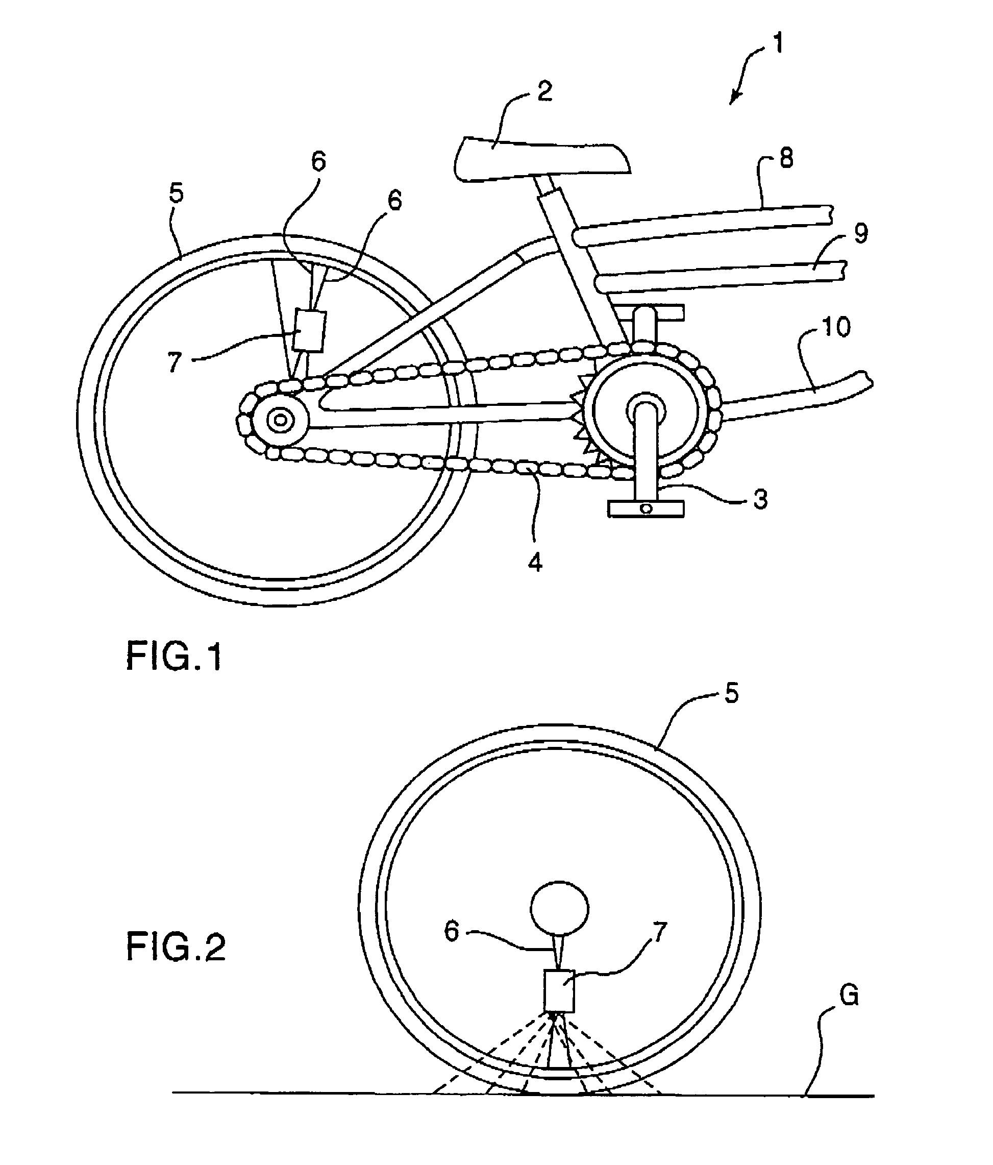
[0022]Referring now to the drawings in greater detail, FIG. 1 shows the present invention 1 attached to the rear wheel 5 of a conventional bike. The bike has the conventional elements such as frame members 8, 9, 10, pedals 3, chain 4, seat 2 and spokes 6 (only some of which are shown in FIG. 1, for clarity). It should be noted that the bike shown in FIG. 1 is a conventional bike, and is not part of the present invention 1. Also, while the light block 7 is shown attached to the rear wheel of the bike, it is not the only place it can be attached. It could be attached instead, or in addition, to the front wheel of the bike.

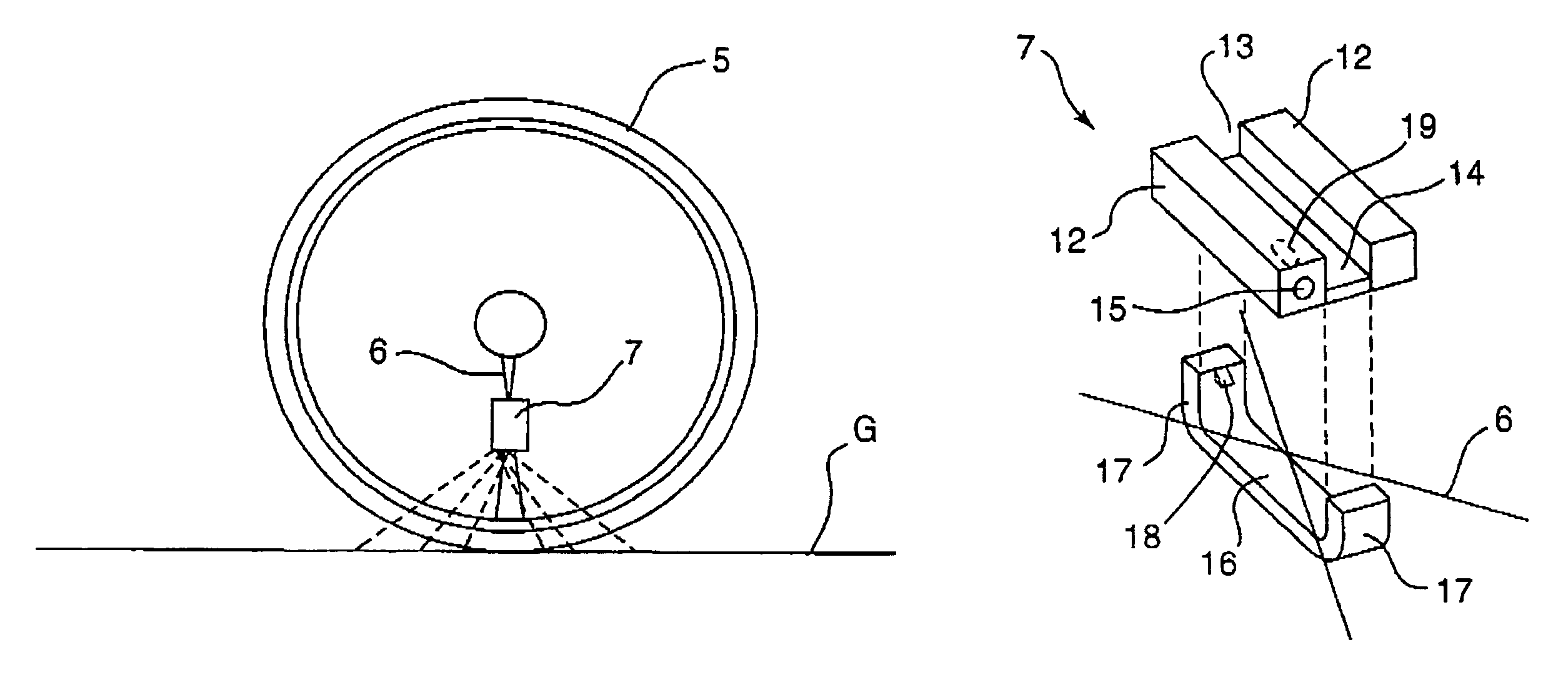
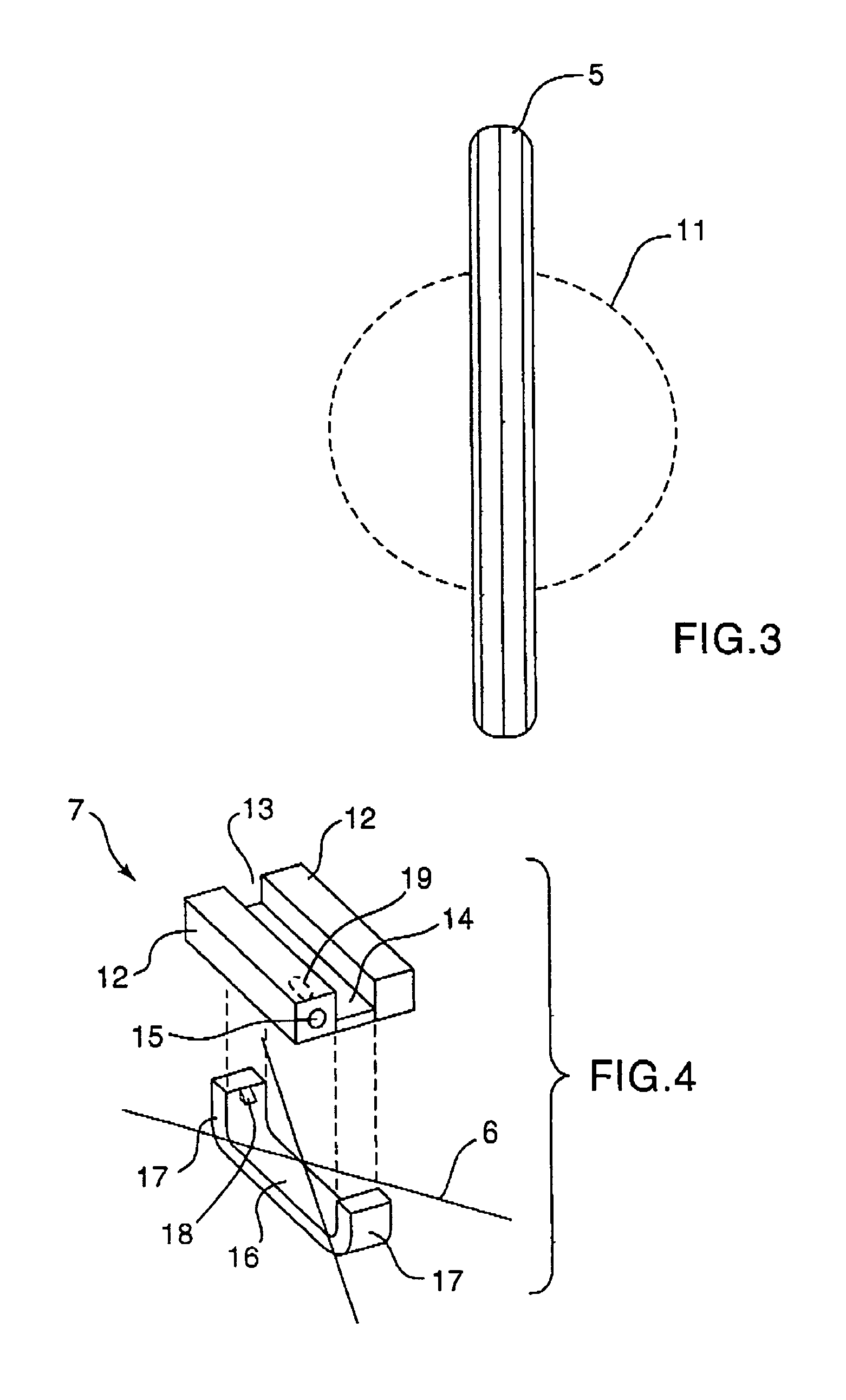
[0023]As shown in FIG. 2, the light block 7 is attached to the spokes 6 such that the light block 7 is mounted in a plane substantially parallel to the plane of the wheel. Since this light block 7 is attached to the spokes 6, the light block 7 will rotate as the wheel 5 rotates. Therefore, the light emanating from the light block 7 (as shown by the dotted lines in FI...


PUM


Abstract

A light which is attached to at least a pair of spokes on a bike wheel by a clip which snaps onto a housing to trap the spokes therebetween.

Description

[0001]Applicant claims priority of Provisional application Ser. No. 60 / 420,781, Filed Oct. 24, 2002.BACKGROUND OF THE INVENTION[0002]This invention relates, in general, to lights, and, in particular, to lights which are attached to bike wheels.DESCRIPTION OF THE PRIOR ART[0003]In the prior art various types of devices have been proposed. For example, U.S. Pat. No. 6,170,968 to Caswell discloses a light attached to the spokes of a bike by means of a threaded fastener.[0004]U.S. Pat. No. 5,803,574 to Szaniszio discloses a light attached to the spokes of a bike by means of a threaded fastener.[0005]U.S. Pat. No. 5,624,175 to Geiormino et al discloses a light attached to the spokes of a bike by means of a spring clip.[0006]U.S. Pat. No. 6,059,431 to Ellis, Jr. discloses a light attached to the spokes of a bike and which has a pair of containers for the batteries that extend at right angles to each other.[0007]U.S. Pat. No. 6,186,635 to Peterson et al discloses a device attached to a bik...

Claims


Application Information

Patent Timeline
IPC IPC(8): B62J6/00
CPCB62J6/20Y10S362/80
Inventor PETERSON, GARY
Owner PETERSON GARY
Why Eureka
Try Eureka