Intelligent directional fire alarm system

a fire alarm system and intelligent technology, applied in the direction of fire alarms, signalling systems, fire alarm smoke/gas actuation, etc., can solve the problems of many deaths and injuries, the presently known alarm system is both expensive and difficult to produce, install and maintain

Inactive Publication Date: 2009-12-01
LACASSE STEVE B
View PDF26 Cites 46 Cited by
  • Summary
  • Abstract
  • Description
  • Claims
  • Application Information

AI Technical Summary

Benefits of technology

[0011]It is an object of the present invention to provide an easily-understandable, highly visible directional lighting system for evacuation within a fire alarm system that does not consume excessive power and which will reliably and effectively produce sufficient light after an initial period of operation.
[0012]It is also an object of the present invention to provide a system that provides information about primary and alternative routes of egress to evacuees on a building-wide level so that all building occupants may evacuate with respect to the relative position of a fire located on any floor or in area of a building.
[0013]It is still a further object of the present invention to provide a system that provides information to firemen and rescuers in such a fashion so as to foster a more comprehensive, overall picture of the location and the magnitude(s) of a fire or fires present in a building.
[0015]To achieve the foregoing and other objects, and in accordance with one aspect of the present invention as broadly described, a directional lighting system for evacuation as part of a broader intelligent fire alarm system is provided through the situation of a substantially linear arrangement of lighting modules along the lengths of corridors and rooms toward exits. It is preferable for the evacuation direction indication system to have arrow shaped lamps in a linear arrangement on a repeated basis throughout a building such that the lamps can be activated so as to show the nearest, safest exit in relation to the fire or fires registered throughout the system. The lamps will be activated by a local and / or centralized activation module when a given fire alarm is alerted by a fire triggered anywhere throughout a building, thereby providing for a comprehensive, unified direction of exiting set for all areas and floor of a building.

Problems solved by technology

However, these systems are generally “dumb” systems that do nothing more than sound a siren or alarm to alert building occupants of a fire, (who must follow unmarked paths to an illuminated “EXIT” sign posted above an exit) and do not provide occupants and / or rescuers with useful escape information based on the relative spatial threat of a fire.
As such, many deaths and injuries occur because of poorly marked exit paths, or because the locally mandated exit signs are obscured by smoke and / or darkness that typically occur during an emergency such as a fire, earthquake, explosion, gas release, black-out, and the like.
Moreover, the presently known alarm systems are both expensive and difficult to produce, install and maintain, and often do not address a variety of emergency situations other than fires.
Furthermore, exit lamps that are used in conjunction with conventional fire alarm systems consume excessive power from battery operated emergency power supply systems and therefore fail to effectively produce sufficient light after an initial period of operation.
In addition, conventional exit lamps are unreliable because they can unpredictably burn out at the time of emergency use.
In addition, the indication lamps and arrangements in conventional systems are difficult to see and understand during emergency situations.
Conventional systems also fail to provide information about alternative routes of egress.
Nevertheless, there have been attempts in the prior art to overcome some of these problems in directing evacuees to exits, but none provide a means to direct evacuees from all areas and floors of a building away from the direction of a fire reported by a fire alarm system.
These types of systems, however, do not offer panicked evacuees a clear sense of direction, given that a laser may point from say, point A to Point B, but cannot show whether one should proceed towards point A, rather than point B, or vice-versa.
Even where such systems attempt to point to a direction by decreasing the slope from say, high to low along the length of a space, for long lengths of corridors, this method does not work as well as in smaller confines.
In any case, however, this approach is fraught with shortcomings in that it is not an immediately obvious, fool-proof means of directing evacuees toward an exit, especially if such evacuees have not been already instructed in the interpretation of such laser points.
However, this approach too, is not immediately intuitive to panicked evacuees who may not understand the meaning of sequenced columns of vertical lights throughout corridors.
However, Minter, does not provide a solution for such notification on a wholesale, building-level approach that can be used to reflect the danger to occupants on other floors / areas from a fire on a different floor / area.
Moreover, Minter does not allow for a system that can provide real-time, large-scale intelligence to firemen and other responders to the scene of an alarm.
Accordingly, none of the other systems in the prior art provide a solution to indicate the safest exit in a universally understandable, intuitive manner such that all evacuees, anywhere in a building, can immediately grasp the correct direction towards an exit relative to a fire (or fires), wherever it (and they) may be located.
In addition, none of the prior art offers intelligent output from such a system, so that firemen and responders can accurately understand the scope of the emergency at hand.

Method used


Image

  • Intelligent directional fire alarm system
  • Intelligent directional fire alarm system
  • Intelligent directional fire alarm system

Examples


Embodiment Construction

[0024]Reference will now be made in detail to the present preferred embodiment of the invention as illustrated in the accompanying drawings.

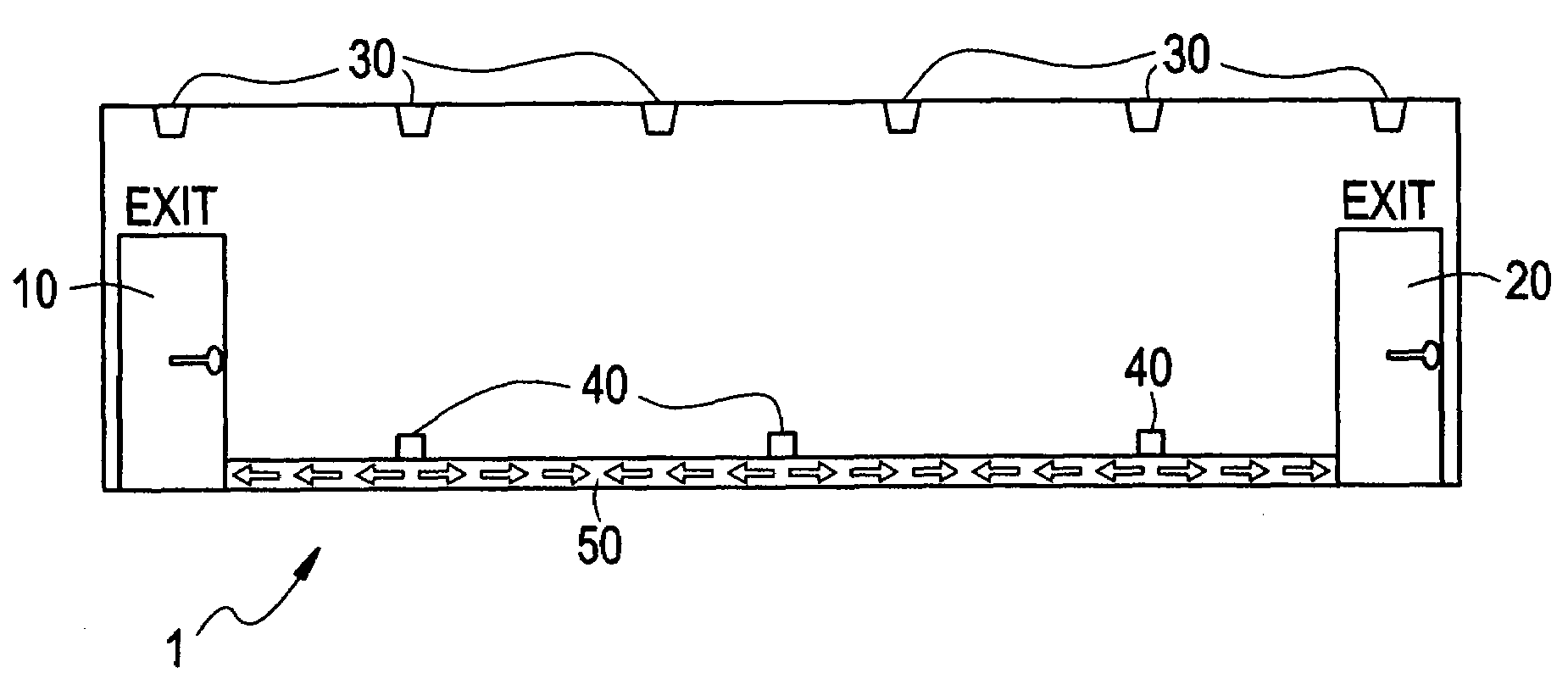
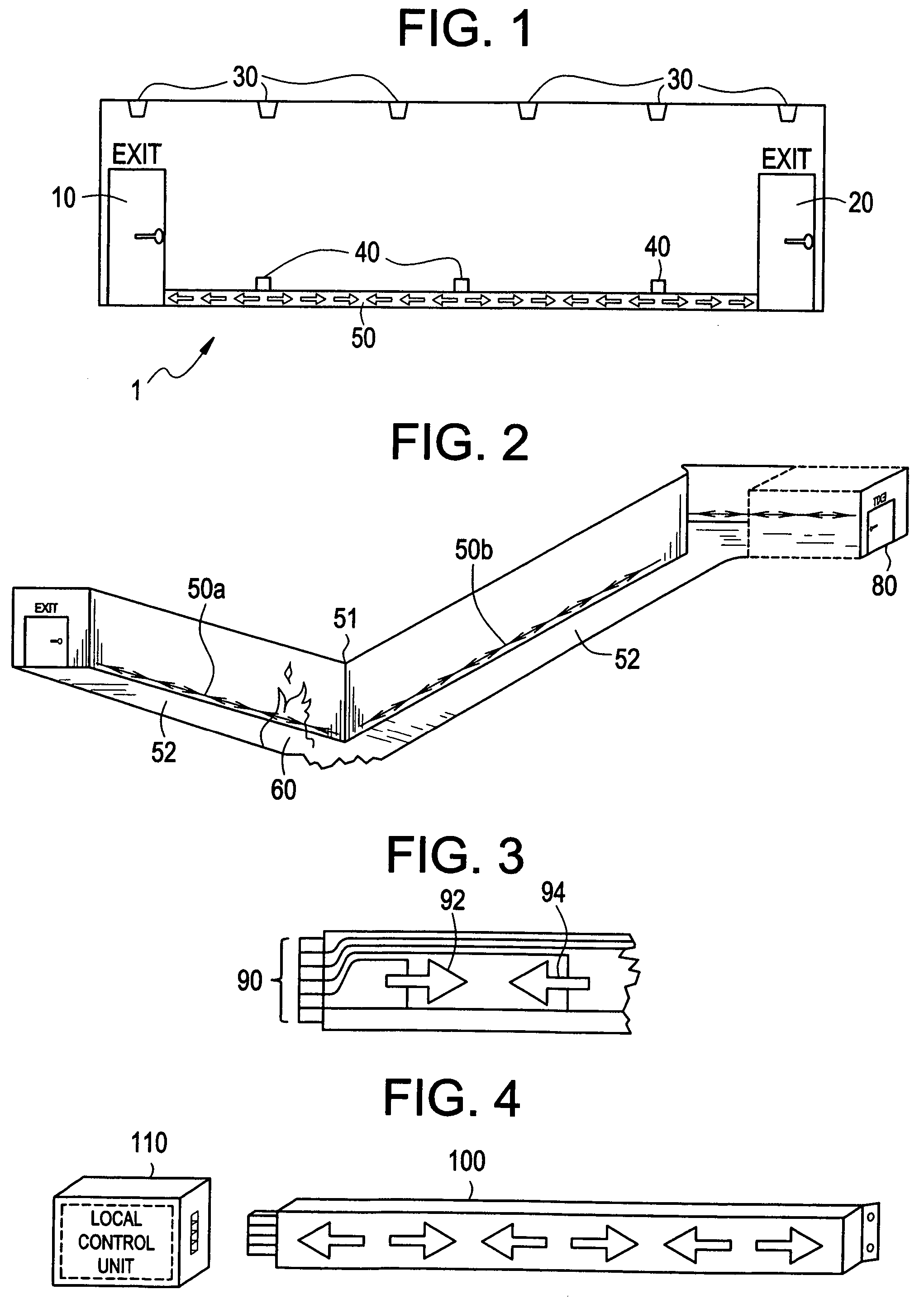
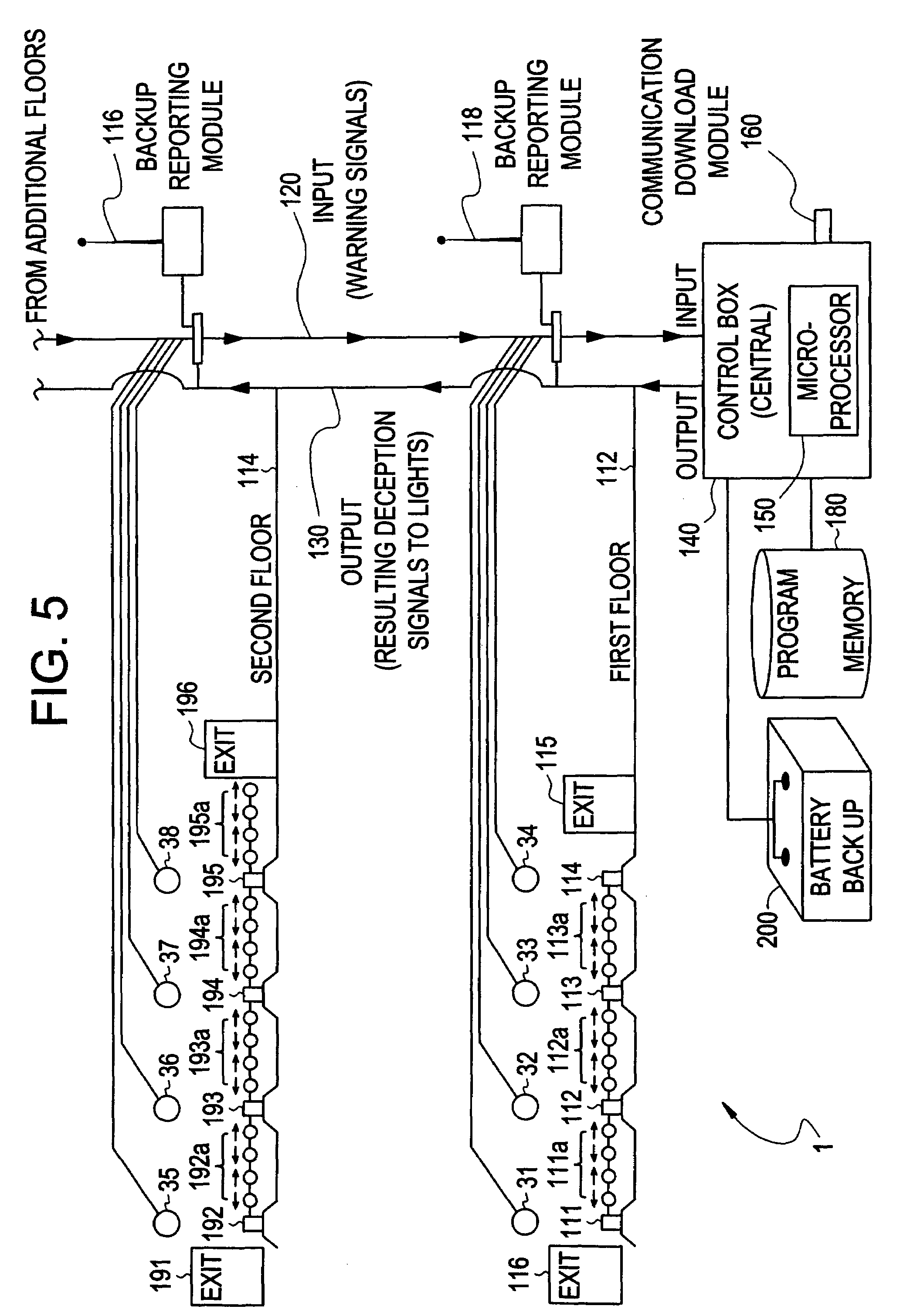
[0025]In accordance with the present invention there is provided an intelligent directional fire alarm system having an evacuation or exit direction indication system, preferably comprising a multiplicity of fire alarm sensors as threat sensing nodes, a multiplicity of indicator units, and directional lighting modules, said directional lighting modules having at least three electroluminescent lamps in a substantially linear arrangement so that the directional lighting modules may be interconnected from end to end, as needed, in order to track the length of rooms and / or corridors towards an exit or exits. Included within such a unit would be a means for potentially illuminating all electroluminescent lamps on a repeated basis in sequential order, from one end of the linear arrangement to the other end of the linear arrangement as a directional in...


PUM


Abstract

An intelligent directional fire alarm system is disclosed. The intelligent directional fire alarm system identifies a threat such as a fire, and the location within a building relative to the known exits for building occupants, and indicates the closest exits in each area of a building relative to the location of an identified threat, and the path towards the exit for evacuees throughout a given building, relative to the detected fire location(s).

Description

RELATED APPLICATIONS[0001]The present application is a Continuation of co-pending PCT Application No. PCT / US05 / 04536, filed on Feb. 14, 2005, which in turn, claims priority from U.S. Provisional Application Ser. No. 60 / 544,374, filed on Feb. 13, 2004. Applicants claim the benefits of 35 U.S.C. §120 as to the PCT application and priority under 35 U.S.C. §119 as to said U.S. Provisional application, and the entire disclosures of both applications are incorporated herein by reference in their entireties.BACKGROUND OF THE INVENTION[0002]1. Field of the Invention[0003]The present invention relates to emergency alarm systems for buildings. More particularly, the present invention relates to a directional fire alarm system for indicating the exit and the path towards the exit for evacuees throughout a given building, relative to the detected fire location(s).[0004]2. Description of the Related Art[0005]It is known in fire fighting circles that when a fire breaks out, time is of the essence...

Claims


Application Information

Patent Timeline
Patent Type & Authority Patents(United States)
IPC IPC(8): G08B17/12G08B5/36G08B7/06
CPCG08B7/062G08B7/064G08B29/188G08B17/00G08B7/066
Inventor LACASSE, STEVE B.
Owner LACASSE STEVE B
Why Eureka
Try Eureka