Image forming apparatus including drive transmission member including gears and shafts

a technology of transmission member and drive transmission, which is applied in the direction of electrographic process apparatus, instruments, optics, etc., can solve the problems of inability to remove the development device when attaching and removing, and achieve the effects of reliable retraction of the development device, low cost and high quality

Inactive Publication Date: 2009-12-01
RICOH KK
View PDF4 Cites 13 Cited by
  • Summary
  • Abstract
  • Description
  • Claims
  • Application Information

AI Technical Summary

Benefits of technology

[0008]According to the above-aspect, as well as enabling a reliable retraction of a development device from a photosensitive member without increasing a number of parts, it is possible to provide a low cost, high quality image forming apparatus. It is possible to reliably attach and detach the development device.

Problems solved by technology

Also, as a plurality of development devices is coupled with respect to one motor, a problem exists wherein a load of a gear train to other coupled development devices makes it impossible to remove the development devices when attaching and removing.

Method used


Image

  • Image forming apparatus including drive transmission member including gears and shafts
  • Image forming apparatus including drive transmission member including gears and shafts
  • Image forming apparatus including drive transmission member including gears and shafts

Examples


embodiment 1

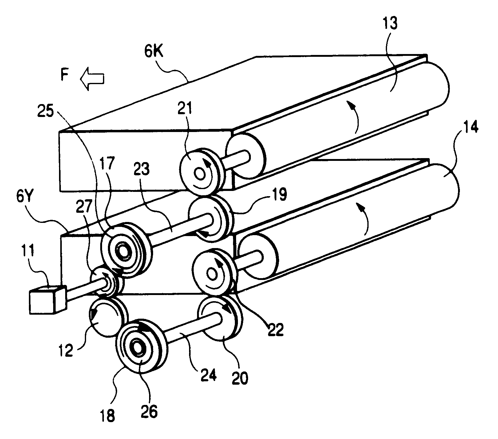
[0015]Hereafter, a description will be given of an embodiment of the invention using FIG. 1 and FIG. 2.

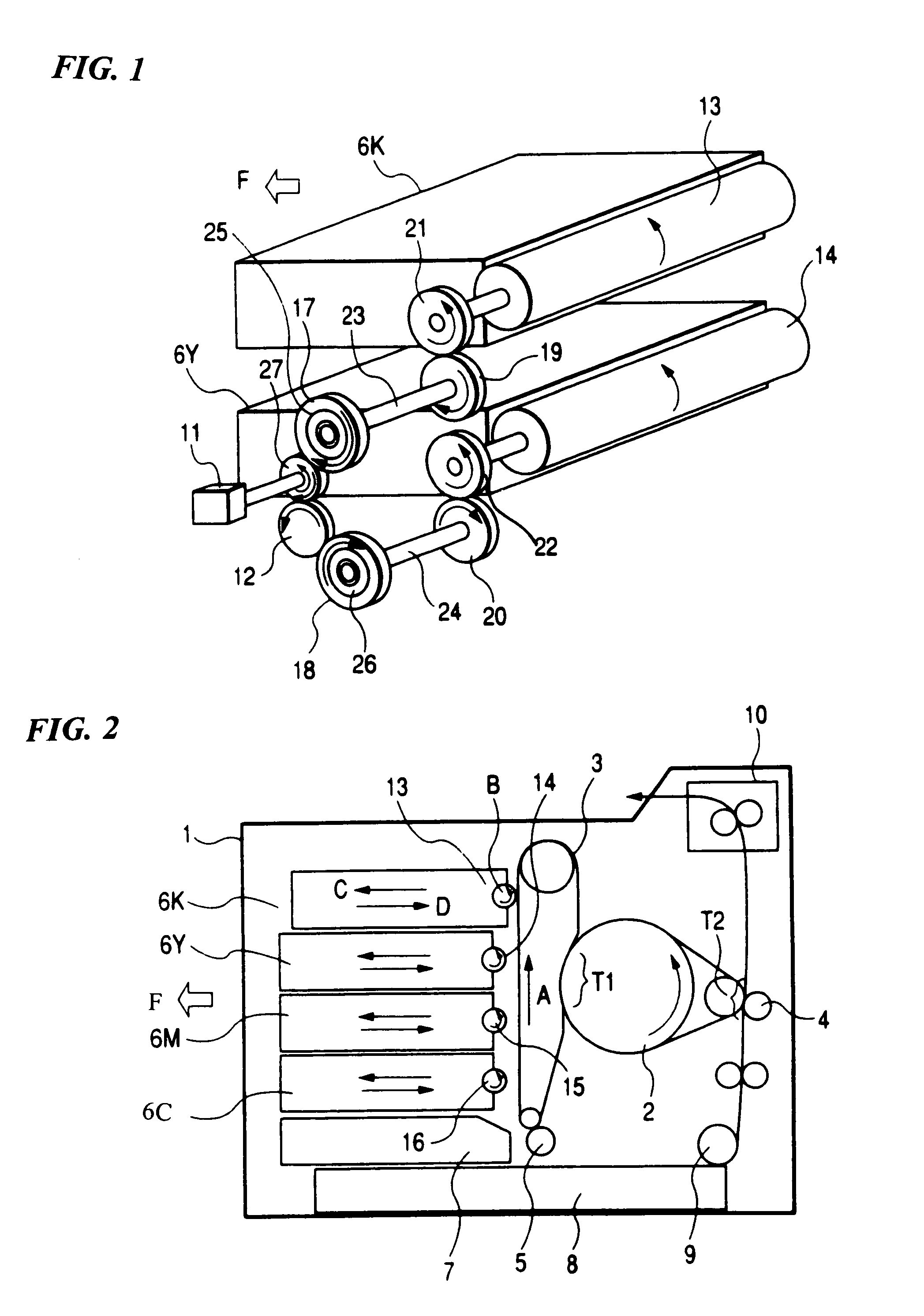
[0016]FIG. 2 is a schematic view of an image forming apparatus 1, which is the embodiment. The apparatus 1 is a color laser printer which is capable of forming a color image by rotating an intermediate transfer body 2 four times, thereby superimposing four colors of image.

[0017]A description will be given of each unit disposed inside the image forming apparatus 1.

[0018]The intermediate transfer body 2 is disposed in a center of the apparatus 1, while a photosensitive member 3 and a transfer device 4 are disposed on a periphery of the intermediate transfer body 2. Also, a charger 5 is disposed on a periphery of the photosensitive member 3. Development devices 6K, 6Y, 6M and 6C, including development rollers 13, 14, 15 and 16 which contain four differing colors of toner and which rotate while making contact with the photosensitive member 3, each being unitized, are disposed in a stac...

embodiment 2

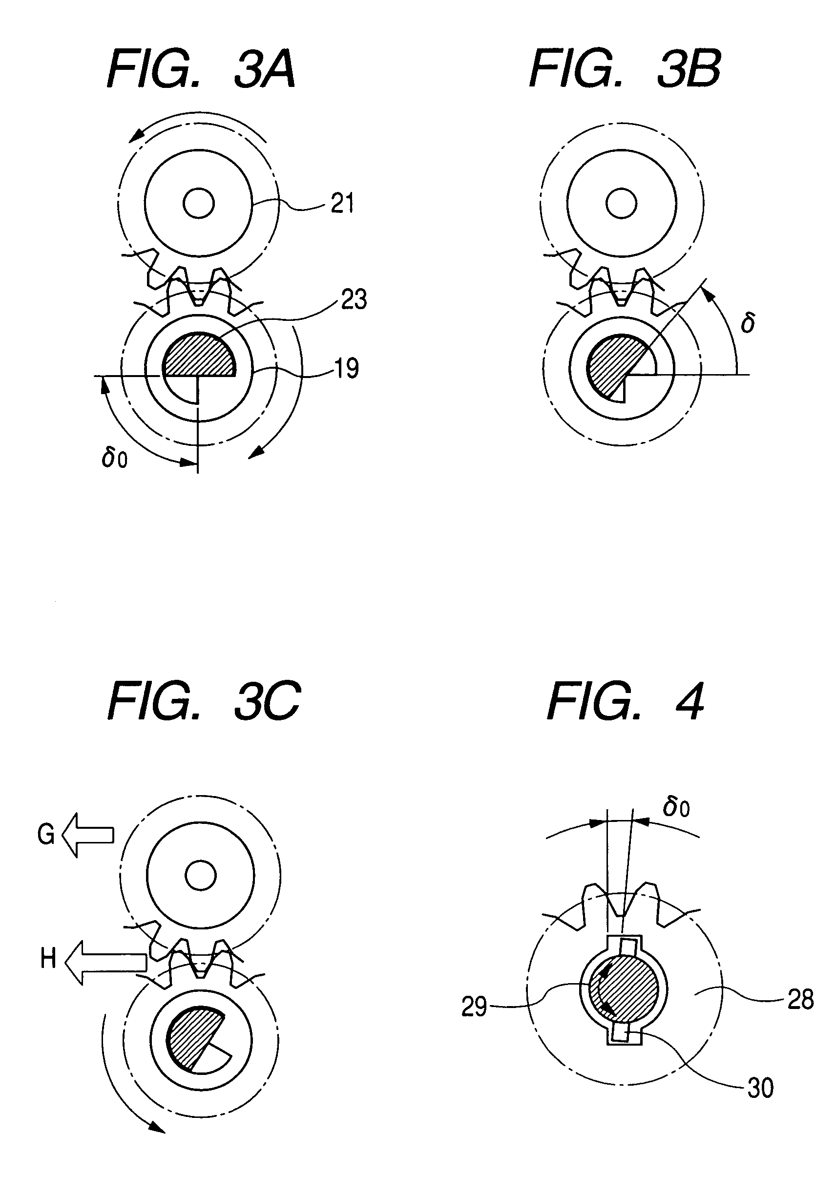
[0028]A description will be given, using FIG. 4, of another embodiment (embodiment 2) of an engagement condition of a shaft and gear according to the embodiment 2. A gear 28, being the development device drive gear 19 in FIG. 1, includes a recession in two places on an inner periphery. A shaft 29, being the shaft 23 which transmits a driving force of the development device drive motor 11, which rotates forward and backwards, in FIG. 1, includes the one-way clutch 25 in FIG. 1 on a not-shown opposite side. Also, a parallel pin 30 is attached to the shaft 29 wherein, as the parallel pin 30 engages with the recessions of the gear 28, an air gap δ0 is formed. Although generally, for reasons of low cost and lightness, a resin molded article made of polyacetal or PPS (polyphenylensulfide) is used for the gear 28, from the point of view of accuracy and strength, a metal is used for the shaft 29. For this reason, as there are two points of contact with the gear 28, it is possible to reduce ...

embodiment 3

[0030]A description will be given, using FIG. 5, of still another embodiment (embodiment 3) of a drive transmission member including an air gap according to the embodiment 3. FIG. 5 shows a condition wherein the shaft 23 shown in FIG. 1 is coupled by two small shafts 31 and 32. That is, an intermediate gear 17, which rotates forward and backwards, as shown by the arrow in the figure, is attached to one side of the small shaft 31 via a one-way clutch 25, while the opposite side is of a D-shape. The shaft 32 is affixed to a development device drive gear 19 without an air gap, while having, on the opposite side, a hollow portion with a projection on an inner surface. Consequently, by aligning and engaging the D-shape of the small shaft 31 and the hollow portion of the small shaft 32, an air gap δ0 is formed. Also, for reasons of accuracy and strength, the small shafts 31 and 32 uses a metal as their material. Consequently, according to this embodiment, even though the D-shape of the sm...


PUM


Abstract

An image forming apparatus includes: a photosensitive member; a plurality of development devices attachable to and detachable from a main body of the image forming apparatus, a motor; and a drive transmission member. Each development device includes a development roller for forming a toner image on a surface of the photosensitive member. The motor is rotatable forward and backward, for driving the development roller. The drive transmission member is disposed between the motor and the development roller. The drive transmission member includes a plurality of gears, a plurality of shafts and a plurality of one-way clutches. An air gap is provided in at least one engagement portion where the gears engage with the shafts.

Description

CROSS-REFERENCE TO RELATED APPLICATIONS[0001]This application is based on and claims the benefit of priority from the prior Japanese Patent Application No. 2005-270077, filed on Sep. 16, 2005; the entire contents of which are incorporated herein by reference.BACKGROUND[0002]1. Technical Field[0003]The present invention relates to an image forming apparatus equipped with development device drive means.[0004]2. Description of Related Art[0005]As an image forming apparatus using an electrophotographic method, such as a copier or a printer, a single component development type image forming apparatus which, by pressing a development roller against a photosensitive member and rotating it, forms a toner inside a development device on the photosensitive member, has been known. Means which rotationally drives the development roller of the image forming apparatus is configured of a motor and a plurality of gears. In a color image forming apparatus which uses a plurality of colors, black, yell...

Claims


Application Information

Patent Timeline
Patent Type & Authority Patents(United States)
IPC IPC(8): G03G15/08
CPCG03G15/0896G03G21/1676G03G21/1647G03G2221/163G03G2221/1657
Inventor OOKUSHI, HIROFUMISAITO, MASAHIKONAKAMURA, KENJIONOSE, ATSUSHI
Owner RICOH KK
Why Eureka
Try Eureka