Dynamically optimized smart antenna system

a smart antenna and dynamic optimization technology, applied in the field of communication networks, can solve problems such as the complexity of data transmission and reception by different apparatus within the network

Inactive Publication Date: 2009-12-01
AIRGAIN INC
View PDF40 Cites 172 Cited by
  • Summary
  • Abstract
  • Description
  • Claims
  • Application Information

AI Technical Summary

Problems solved by technology

Furthermore, in a typical mobile wireless network, the locations of at least some of the communications apparatus are not fixed with respect to each other, thereby further complicating the transmission and reception of data by different apparatus within the network.

Method used


Image

  • Dynamically optimized smart antenna system
  • Dynamically optimized smart antenna system
  • Dynamically optimized smart antenna system

Examples


Embodiment Construction

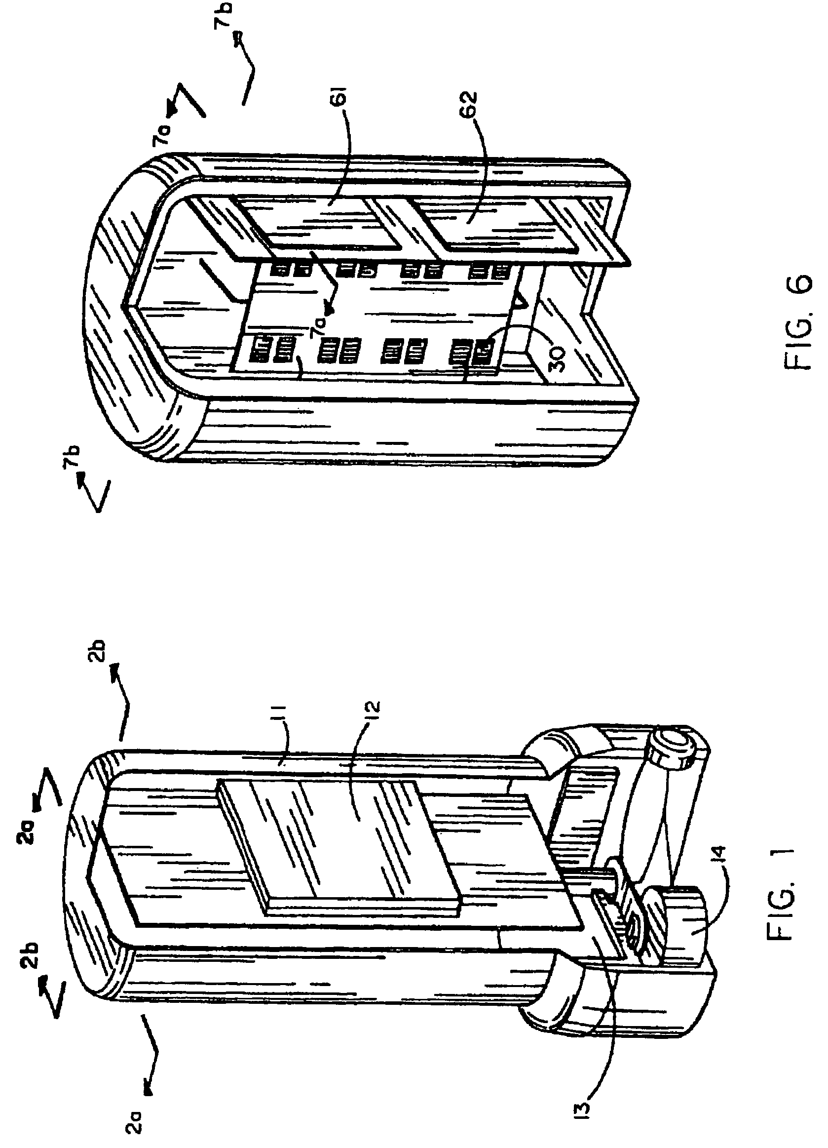
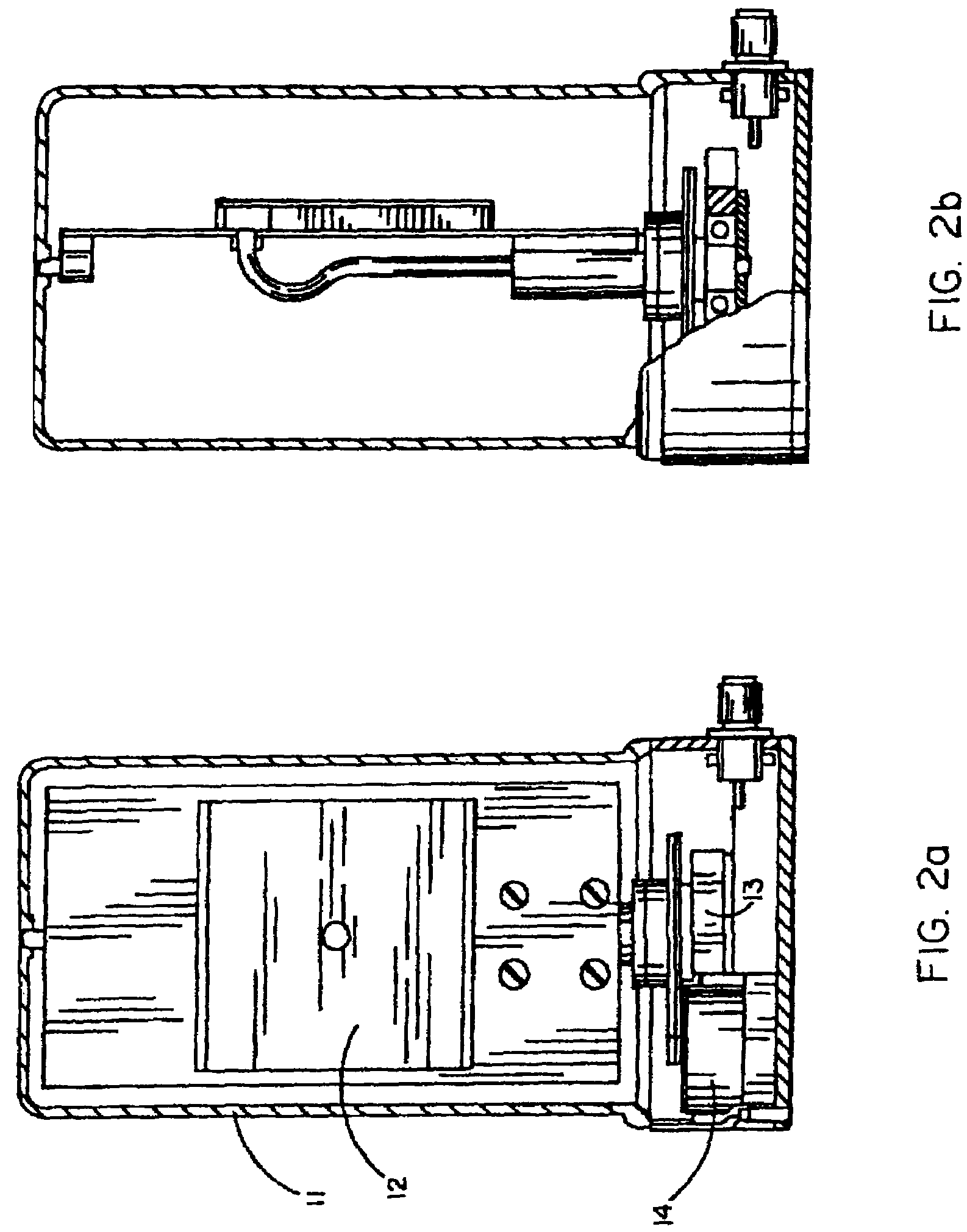
[0022]FIG. 1 shows a partially cutaway perspective view of an embodiment of a direction-agile antenna system for use in a mobile wireless communications network. In this embodiment, the antenna system includes a mechanically steered antenna 12 enclosed within a dielectric cover 11. A motor driver 13 is connected to a motor 14 which is capable of rotating the antenna 12 to a desired direction. In an embodiment, the motor 14 is capable of rotating the antenna 12 through 360° in azimuth to scan the antenna beam in a horizontal plane. In a further embodiment, the motor driver 13 is capable of driving the antenna 12 to scan in both azimuth and elevation.

[0023]In an embodiment, the antenna 12 is a planar microstrip antenna which comprises a plurality of microstrip antenna elements capable of transmitting and receiving electromagnetic signals in a direction having a positive antenna gain. Other types of directional antennas with positive antenna gains in desired directions may also be impl...


PUM


Abstract

A wireless communications network includes a plurality of wireless devices equipped with direction-agile antenna systems to allow the wireless devices to establish and maintain wireless data links with each other.

Description

RELATED APPLICATION [0001]This is a continuation application of U.S. patent application Ser. No. 09 / 709,758, filed on Nov. 10, 2000 now U.S. Pat. No. 7,162,273, which is incorporated herein by reference in its entirety.FIELD OF THE INVENTION[0002]The present invention relates to a communications network, and more particularly, to a wireless communications network.BACKGROUND ART[0003]Omni-directional antennas have been implemented in various types of mobile communications devices in a conventional wireless network, for example, a digital mobile telephone network. In addition to voice communications, attempts have been made to provide high speed data communications between various types of apparatus including, for example, desktop computers, laptop computers, servers, peripherals and power management hubs in a wireless network. Compared to voice communications, data communications typically require a large bandwidth, a very low bit error rate, and ability to communicate with multiple ...

Claims


Application Information

Patent Timeline
Patent Type & Authority Patents(United States)
IPC IPC(8): H04B1/40H01Q3/00
CPCH01Q3/04H01Q9/0407H01Q3/24
Inventor ABRAMOV, OLEG Y.KASHKAROV, ALEXANDER G.KIRDIN, ALEXANDER N.
Owner AIRGAIN INC
Why Eureka
Try Eureka