Rock drilling device

Inactive Publication Date: 2009-12-08
ATLAS COPCO ROCK DRILLS
21 Cites 2 Cited by

AI-Extracted Technical Summary

Problems solved by technology

This method has that drawback that the lubrication will be dependent on the pivot angle of the rock drilling machine with respect t...

Benefits of technology

[0003]The present invention, as defined in the following patent claim, aims at providing a rock drilling device...

Abstract

A rock drilling machine includes a sleeve having openings surrounding a portion of a lubrication channel. A groove surrounds the sleeve, and one end of a second channel is connected to the groove. The other end of the second channel is connected to a lubrication point so that lubricant from the lubrication channel is distributed from the lubrication channel, through the sleeve and groove to the second channel, and from the second channel to a lubrication point of the rock drilling machine.

Application Domain

ConstructionsOperator-supported drilling machines +3

Technology Topic

LubricationEngineering +2

Image

  • Rock drilling device
  • Rock drilling device

Examples

  • Experimental program(1)

Example

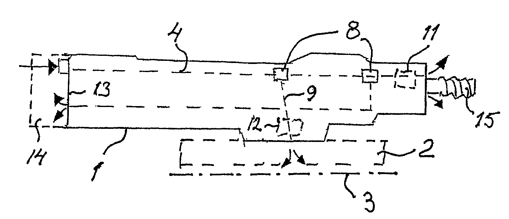
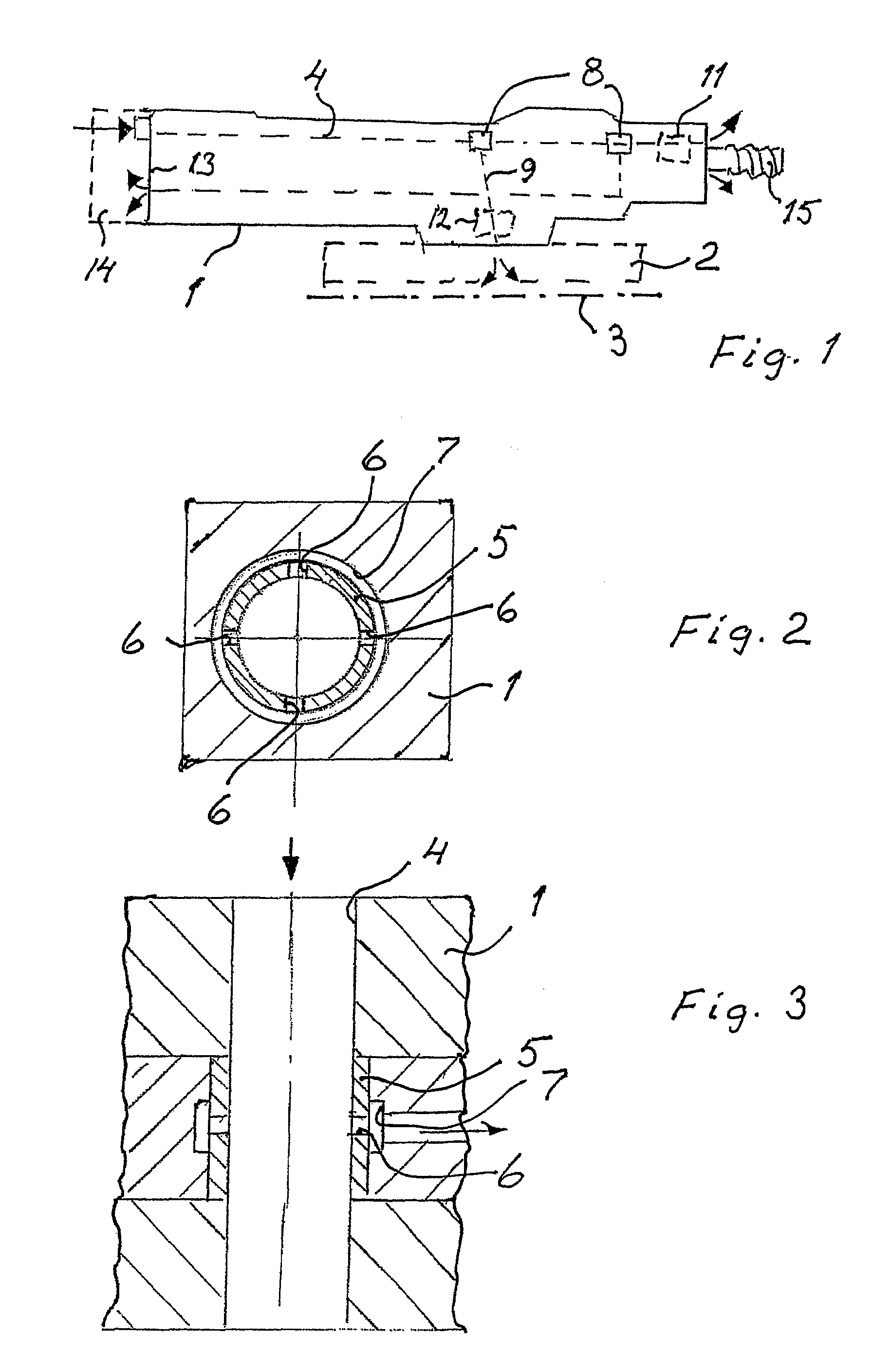
[0008]The rock drilling device shown on the drawing includes a rock drilling machine 1, which is movable forwards and backwards along a feed beam 2. The rock drilling machine 1 and the feed beam 2 are pivotal around an axis 3 which extends along the feed beam 2. A channel 4 is leading through the rock drilling machine 2 for supply of lubricant to different points of lubrication. This is achieved by means of oil-rich air. In the channel 4 there are a number of distributors 8 for distributing the lubrication air between the channel 4 and a further channel 9 which leads to the point of lubrication. In the shown example lubrication takes place of a front guide 11, a follower device 12 for rotation of a drilling tool 15 and a parting plane 13 between the main body of the rock drilling machine 1 and a rear portion 14. The construction of the distributors 8 is shown in more detail in FIGS. 2 and 3.
[0009]The distributor 8 includes a sleeve 5 which is positioned inside the channel 4, said sleeve being provided with a number of generally radial holes 6, distributed along the circumference of the sleeve 5. Around the sleeve 5 is arranged a groove 7 which connects the radial holes 6. The holes 6 are dimensioned in such a way that a suitable portion of the lubricant leaves the channel 4 through the radial holes 6 to the channel 9 and a point of lubrication connected thereto.

PUM

no PUM

Description & Claims & Application Information

We can also present the details of the Description, Claims and Application information to help users get a comprehensive understanding of the technical details of the patent, such as background art, summary of invention, brief description of drawings, description of embodiments, and other original content. On the other hand, users can also determine the specific scope of protection of the technology through the list of claims; as well as understand the changes in the life cycle of the technology with the presentation of the patent timeline. Login to view more.
Why Eureka
Try Eureka