Steering device

a steering device and cable technology, applied in electrical steering, mechanical equipment, transportation and packaging, etc., can solve the problems of cumbersome operation and large number of steps, and achieve the effect of adjusting the tension of cables

Inactive Publication Date: 2009-12-08
NISSAN MOTOR CO LTD
View PDF13 Cites 54 Cited by
  • Summary
  • Abstract
  • Description
  • Claims
  • Application Information

AI Technical Summary

Benefits of technology

[0007]The present invention relates to overcoming the disadvantages of the related cable-based steering device and providing a cable-based steering device in which the tensions of cables may be adjusted using a quick and simple cable tension adjustment operation.
[0012]In accordance with yet a further aspect of an embodiment of the invention, there is provided a steering device including first and second cables, first and second sheaths, and an adjusting means. The first cable is at least partially wound on a first cable pulley in a first direction of rotation of the first cable pulley. The second cable is at least partially wound on the first cable pulley in a second direction of rotation of the first cable pulley. The first sheath extends between first and second ends, with the first cable slidingly disposed in the first sheath. The second sheath extends also between first and second ends, with the second cable slidingly disposed in the second sheath. The first ends of both the first and second sheaths are disposed proximate to the first cable pulley. The adjusting means provides simultaneous adjustment of a relative displacement between the first cable pulley and each of the first ends of the first and second sheaths.
[0013]Thus, adjusting the tensions of the cables may be achieved quickly and easily in response to moving the pulley supporting part and the cable supporting part relative to each other. This is in contrast to the related cable-based steering device wherein adjusting the tensions of the cables requires a cumbersome and time-consuming operation that includes independently adjusting the separate adjustment nuts.

Problems solved by technology

The related cable-based steering device suffers from a number of disadvantages including that, in setting the tension of the cables, each of the two adjustment nuts needs to be separately adjusted while the steering gear mechanism and the steering wheel are both in the neutral state.
This is a cumbersome operation that requires a large number of steps.

Method used


Image

  • Steering device
  • Steering device
  • Steering device

Examples


second embodiment

[0076]According to a second embodiment of a steering device, smooth turning of sliding screw shaft 80 is provided by threaded engagement on only one portion of screw shaft 80. Because the overall configuration of the second embodiment is generally similar to that of the first embodiment, and particularly the overall configuration shown in FIG. 1, only differences will be explained in detail.

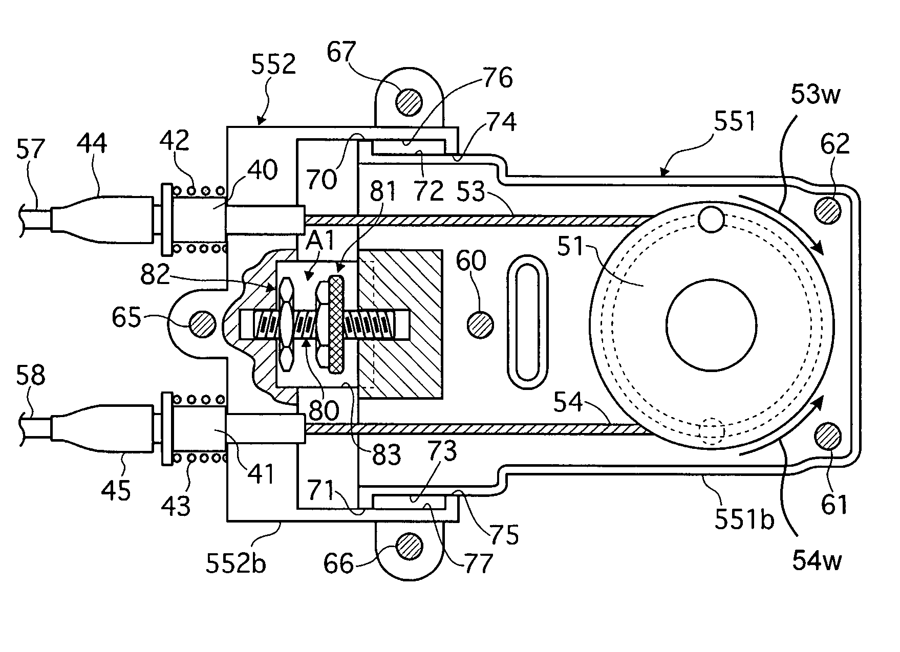
[0077]FIG. 9 shows an enlarged cross sectional view of a second cable tension adjustment mechanism A2. Second cable tension adjustment mechanism A2 includes a knurled nut 81 that is fixed at approximately the center of screw shaft 80, which is preferably disposed laterally between cables 53, 54. As in the first embodiment, knurled nut 81 provides the turning operation member for directly turning screw shaft 80. Locking nut 82 threadingly engages first threaded part 80a of screw shaft 80, and is locked when it is tightened so as to abuttingly engage pulley supporting part 551. In contrast to the f...

third embodiment

[0082]According to a third embodiment of a steering device, worm wheels are fixed at approximately the center of each of two screw shafts, engaging the worm wheels are worm gears that are provided on a worm gear shaft, and an adjustment knob that is provided at an end of the worm gear shaft carries out the adjustment operation from a side surface of a pulley case. Because the overall configuration of the third embodiment is generally similar to that of the second embodiment, and particularly the overall configuration shown in FIG. 9, only differences will be explained in detail.

[0083]FIGS. 10 and 11 show cross sectional views of a third cable tension adjustment mechanism A3. Third cable tension adjustment mechanism A3 includes a pair of worm wheels 85 and 85 that are fixed at approximately the respective centers of each of a pair of screw shafts 80 and 80, and are disposed generally parallel to cables 53, 54. Third cable tension adjustment mechanism A3 also includes a pair of worm g...

fourth embodiment

[0093]According to a fourth embodiment of a steering device, a worm wheel is fixed at approximately the center of a screw shaft, a worm gear engages the worm wheel and is fixed on a worm gear shaft that extends perpendicularly to an imaginary plane between first ends of a pair of cables, and an adjustment knob is provided at an end of the worm shaft. The worm gear shaft is turned with respect to at least one of the upper and lower surfaces of the pulley case in order to carry out an adjustment operation. Because the overall configuration of the fourth embodiment is generally similar to that of the second embodiment, and particularly the overall configuration shown in FIG. 9, only differences will be explained in detail.

[0094]FIGS. 12 and 13 show cross sectional views of a fourth cable tension adjustment mechanism A4. Fourth cable tension adjustment mechanism A4 includes a worm wheel 85 fixed at approximately the center of a single screw shaft 80, which is disposed approximately midw...


PUM


Abstract

A steering device includes a first housing, first and second cables, and first and second sheaths. The first housing includes a first part that supports a rotatable first cable pulley, and a second part that is disposed for relative displacement with respect to the first part. The first cable is at least partially wound on the first cable pulley in a first direction of rotation. The second cable is at least partially wound on the first cable pulley in a second direction of rotation. The first sheath surrounds the first cable and extends between first and second ends, and the first end of the first sheath is coupled to the second part of the first housing. The second sheath surrounds the second cable and extends between first and second ends, and the first end of the second sheath is coupled to the second part of the first housing.

Description

CROSS-REFERENCE TO RELATED APPLICATIONS[0001]This application claims priority under 35 U.S.C. §119 to Japanese Patent Application No. 2006-057269, filed on Mar. 3, 2006, the disclosure of which is incorporated by reference herein in its entirety.BACKGROUND OF THE INVENTION[0002]1. Field of the Invention[0003]The present invention pertains to the technical field of cable-based steering devices in which a steering wheel and a steering gear mechanism are connected using actuation cables, such as Bowden cables.[0004]2. Description of Related Art[0005]In a related cable-based steering device, a steering wheel and a steering gear mechanism are connected using two actuation cables in which a cable extends through a sheath. In the related cable-based steering device, a tension adjustment mechanism adjusts the tensions of the cables while the steering wheel and the steering gear mechanism are in the neutral state, i.e., the steering wheel and the steering gear mechanism are centered. Tension...

Claims


Application Information

Patent Timeline
Patent Type & Authority Patents(United States)
IPC IPC(8): F16C1/10
CPCB62D1/163F16C1/262F16C1/18F16C1/106Y10T74/20402F16C2326/24
Inventor CHINO, NAOTAKAKUBOKAWA, NORIKIEGUCHI, TAKAAKI
Owner NISSAN MOTOR CO LTD
Why Eureka
Try Eureka