Fiber optic plug assembly with boot and crimp band

a fiber optic plug and connector technology, applied in the field of fiber optic connector assemblies, can solve the problems of increased cost of heat shrink seal, inability to meet the needs of use, and material shrinkage, and achieve the effect of simple hardware and convenient installation of the plug assembly

Active Publication Date: 2009-12-08
CORNING OPTICAL COMM LLC
View PDF20 Cites 43 Cited by
  • Summary
  • Abstract
  • Description
  • Claims
  • Application Information

AI Technical Summary

Benefits of technology

[0009]To achieve the forgoing and other objects, and in accordance with the purposes of the present invention as embodied and broadly described herein, the present invention provides various embodiments of a fiber optic plug assembly and plug assembly components including a crimp-on pre-molded boot and O-ring between a buffer tube on a drop cable and a crimp body in the plug assembly. Advantageously, the present invention eliminates an overmolded boot, providing a more readily installed plug assembly. Further, the present invention eliminates the need to perform a heat shrink between the buffer tube and crimp body by using an internal O-ring. The present invention does not require significant investments in molds and presses to install the connector assembly. The plug assembly of the present invention meets the demanding standards specified in GR-3120-CORE while at the same time providing a more simple hardware package that can be assembled with ordinary tools.
[0010]In one exemplary embodiment, the present invention provides a hardened fiber optic plug assembly including: a fiber optic plug mounted upon an end of a fiber optic cable, a pre-molded boot placed over the fiber optic plug and the fiber optic cable, and a crimp band mated over the pre-molded boot to secure the boot to the fiber optic cable, wherein the fiber optic plug assembly is operable to mate to a fiber optic receptacle, fiber optic plug or other hardware or device. The hardened fiber optic plug assembly further includes a buffer tube at the end of the fiber optic cable, an O-ring located on the buffer tube, and an O-ring pusher tube located on the buffer tube behind the O-ring relative to the end of the fiber optic cable, wherein the pusher tube is operable to seat the O-ring between the buffer tube and a crimp body created by the crimp band and pre-molded boot. The O-ring is operable to seal the plug assembly, and wherein the O-ring pusher tube provides protection for the buffer tube. The plug assembly substantially meets GR-3120-CORE specifications. Optionally, the pre-molded boot includes rubber or other elastomeric material, and the crimp band includes brass or other deformable material. The boot and crimp band together provide sealing and strain relief such that the plug assembly substantially meets GR-3120-CORE specifications. The hardened fiber optic plug assembly further includes a stamped metallic strength element engaged between the crimp band and the pre-molded boot. Optionally, the stamped metallic strength element is made to the pre-molded boot.
[0012]In yet another exemplary embodiment, the present invention provides a fiber optic plug assembly including: a plug sub-assembly mated to a plurality of optical fibers in a fiber optic cable, a plug outer housing located substantially over the plug sub-assembly, a pre-molded boot located substantially over the plug sub-assembly and the fiber optic cable, and a crimp band mated over the pre-molded boot to secure the boot to the fiber optic cable and to seal the fiber optic plug. The plug assembly substantially meets GR-3120-CORE specifications. The fiber optic plug assembly further includes a coupling nut located over the plug outer house and operable to mate with a fiber optic receptacle. The outer housing includes a key slot for aligning the plug with the receptacle. Optionally, the fiber optic plug assembly further includes a buffer tube at the end of the fiber optic cable, an O-ring located on the buffer tube, an O-ring pusher tube located on the buffer tube behind the O-ring relative to the end of the fiber optic cable, wherein the pusher tube is operable to seat the O-ring between the buffer tube and a crimp body created by the crimp band and pre-molded boot. The O-ring is operable to seal the plug assembly, and wherein the O-ring pusher tube provides protection for the buffer tube. Optionally, the boot is provided with a port for introducing adhesive. Optionally, splines are added to the large inner diameter of the slide-up boot to prevent adhesive from flowing during its liquid stage.

Problems solved by technology

The heat shrink seal has increased cost and is not as robust as an overmolded boot.
A glue body material is injected between a buffer tube and a crimp body, but leakage occurs due to shrinkage of the material.
Additionally, the overmolded boot material is very stiff to meet the GR-3120-CORE side load requirement, thus the overmolded boot material melt temperatures are high, resulting in damage to the buffer tube further complicating sealing when the overmolded boot, crimp body, and buffer tube are heated to form a seal.
However, these solutions are not simple to execute in a typical cable assembly house or in the field.

Method used


Image

  • Fiber optic plug assembly with boot and crimp band
  • Fiber optic plug assembly with boot and crimp band
  • Fiber optic plug assembly with boot and crimp band

Examples


Embodiment Construction

[0029]The present invention will now be described more fully hereinafter with reference to the accompanying drawings in which exemplary embodiments of the invention are shown. However, this invention may be embodied in many different forms and should not be construed as limited to the embodiments set forth herein. These exemplary embodiments are provided so that this disclosure will be both thorough and complete, and will fully convey the scope of the invention to those skilled in the art.

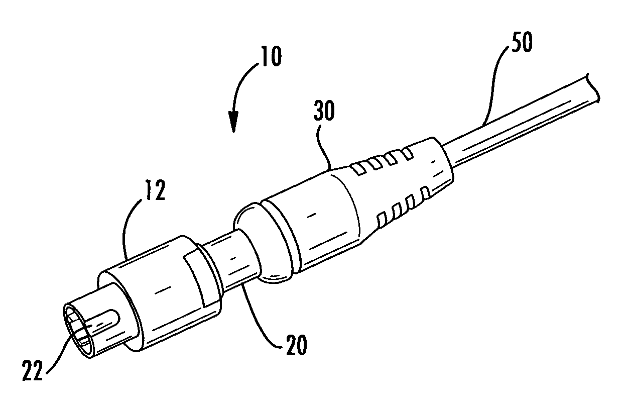
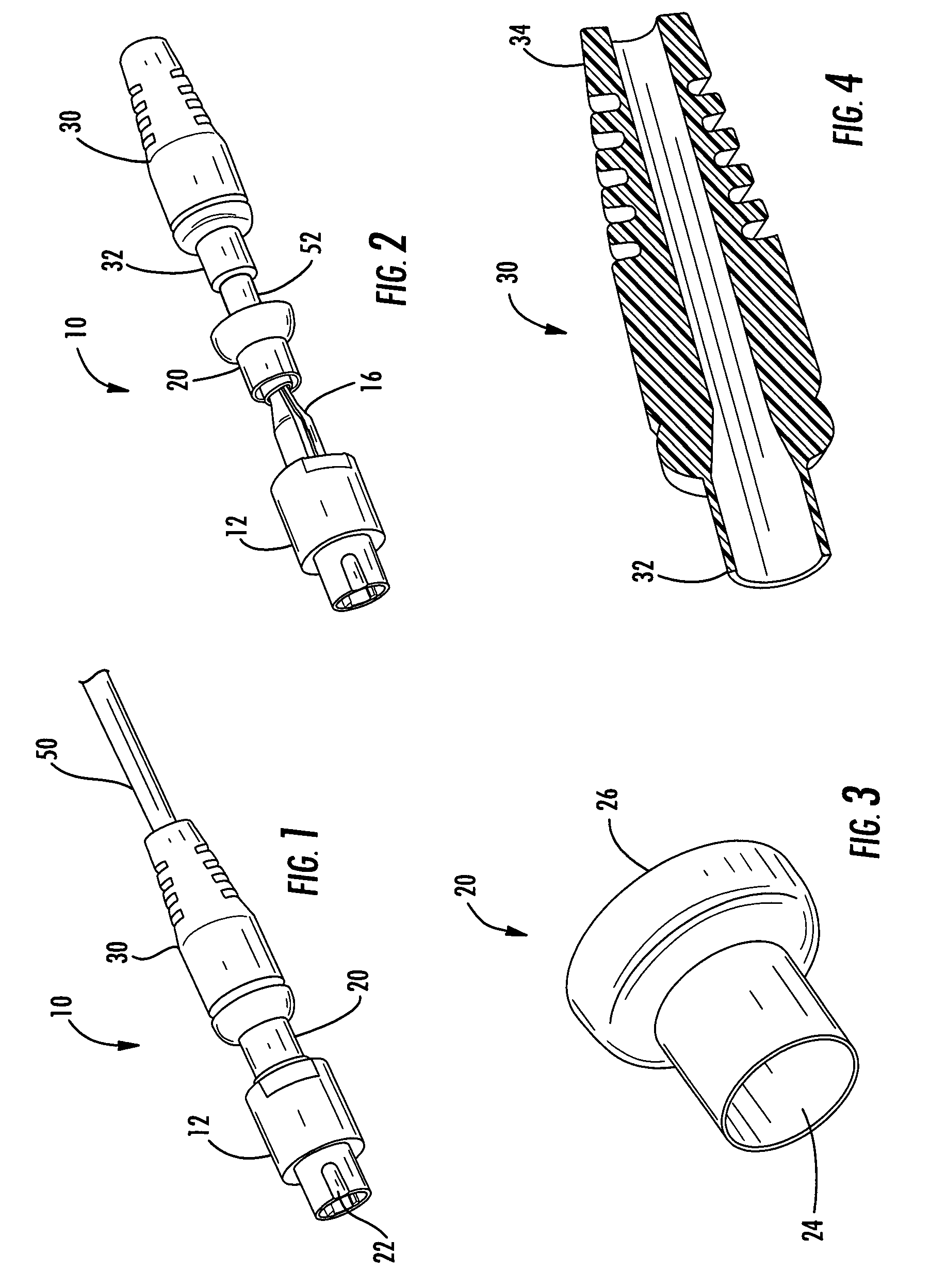
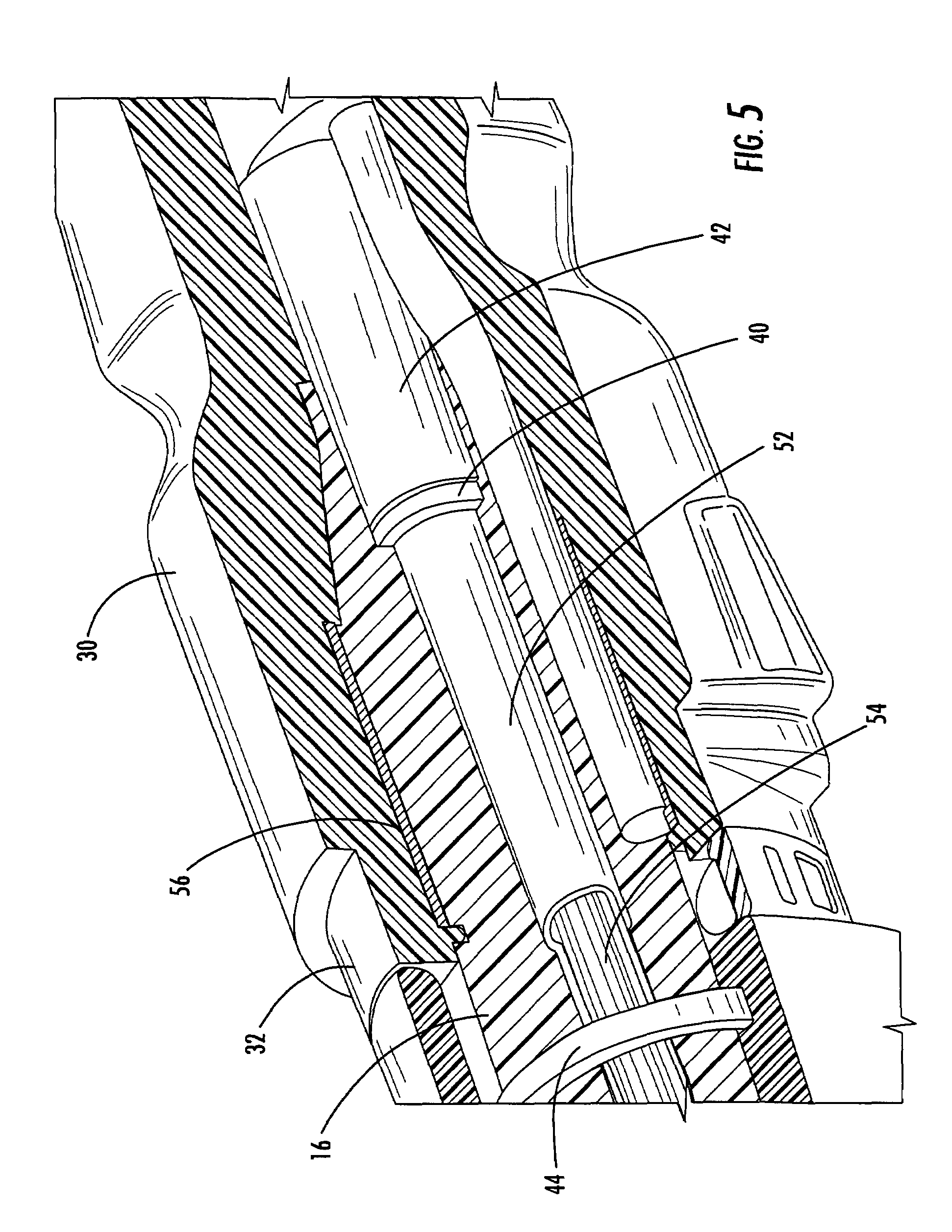
[0030]In the various embodiments described below, the present invention provides a crimp-on pre-molded boot and O-ring between a buffer tube on a drop cable and a crimp body in the plug assembly of a fiber optic connector assembly. Advantageously and in various exemplary embodiments described herein, the present invention eliminates an overmolded boot, providing a simpler to install connector assembly. Further, the present invention eliminates the need to perform a heat shrink between the buffer tu...


PUM


Abstract

A fiber optic plug assembly of a fiber optic connector assembly is provided and generally includes a fiber optic plug mounted upon an end of a fiber optic cable; a pre-molded boot placed over the fiber optic plug and the fiber optic cable; and a crimp band mated over the pre-molded boot to secure the boot to the fiber optic cable; wherein the fiber optic plug assembly is operable to mate to a fiber optic receptacle. The plug assembly eliminates the need for an overmolded boot. Further, the present invention eliminates the need to perform a heat shrink between the buffer tube and crimp body through the internal O-ring. The plug assembly meets the standards of GR-3120-CORE while at the same time providing a simpler hardware package that can be assembled with ordinary connectorization tools.

Description

CROSS-REFERENCE TO RELATED APPLICATION(S)[0001]This Application incorporates by reference in its entirety for all purposes commonly assigned U.S. patent application Ser. No. 10 / 924,525 filed Aug. 24, 2004, and entitled “FIBER OPTIC RECEPTACLE AND PLUG ASSEMBLIES.” Furthermore, this Application incorporates by reference in its entirety for all purposes commonly assigned U.S. patent application Ser. No. 11 / 076,684 filed Mar. 10, 2005, and entitled “MULTI-FIBER FIBER OPTIC RECEPTACLE AND PLUG ASSEMBLY.”BACKGROUND OF THE INVENTION[0002]1. Field of the Invention[0003]The present invention relates generally to fiber optic connector assemblies, and more specifically, to fiber optic connector assemblies with a field-installable crimp-on boot and an O-ring on a plug assembly for interconnecting optical fibers within a fiber optic communications network.[0004]2. Technical Background of the Invention[0005]Optical fiber is increasingly being used for a variety of broadband applications includin...

Claims


Application Information

Patent Timeline
Patent Type & Authority Patents(United States)
IPC IPC(8): G02B6/38G02B6/36
CPCG02B6/3887G02B6/3889G02B6/38875
Inventor CODY, JOSEPH TODDLUTHER, JAMES PHILLIPLEWALLEN, CHRISTOPHER PAULTHEUERKORN, THOMAS
Owner CORNING OPTICAL COMM LLC
Why Eureka
Try Eureka