Pedal assembly for percussion instrument

Inactive Publication Date: 2009-12-08
LIN HSI TAN
View PDF1 Cites 12 Cited by
  • Summary
  • Abstract
  • Description
  • Claims
  • Application Information

AI Technical Summary

Benefits of technology

[0013]The primary object of the present invention is to provide a pedal assembly which is composed of frames, a front board and a rear board, where

Problems solved by technology

The conventional board 73 is usually heavy so that it is difficult to transport the pedal assembly.
Besides, the conventional pedal assembly requires a lot of time to be assembled and dis-assembled.
Also, the heavy board 73 needs too much material which means h

Method used


Image

  • Pedal assembly for percussion instrument
  • Pedal assembly for percussion instrument
  • Pedal assembly for percussion instrument

Examples


Example

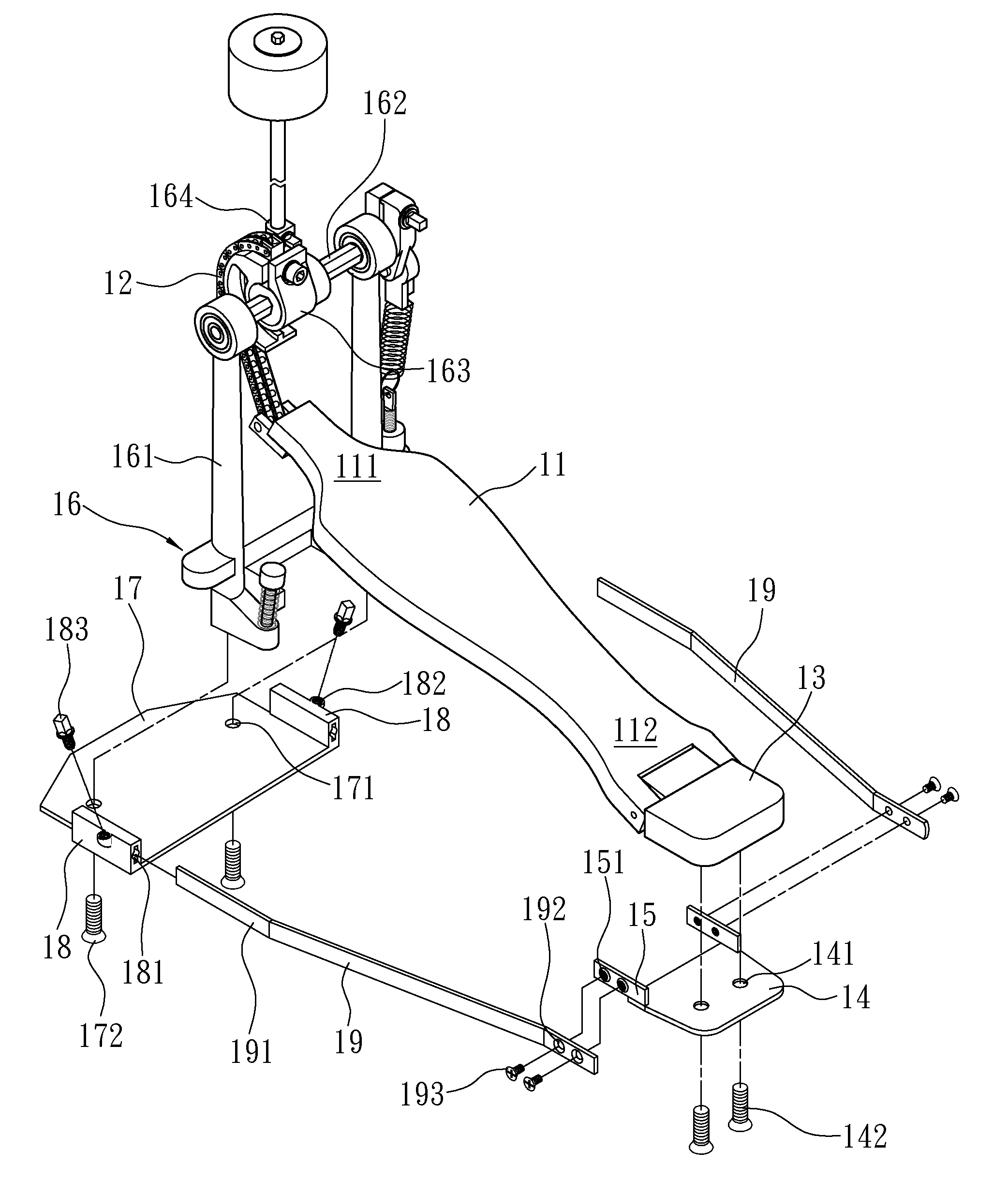
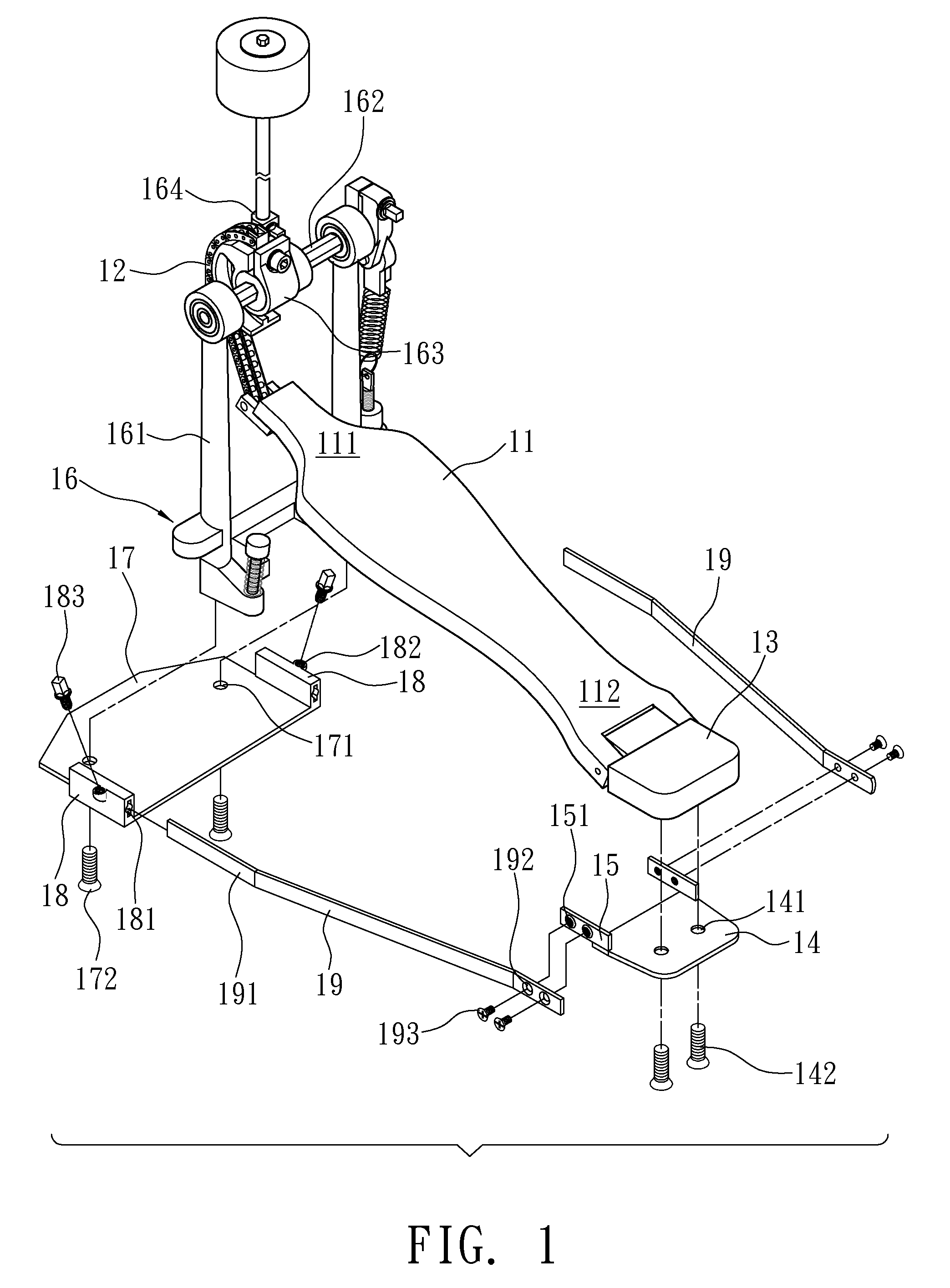
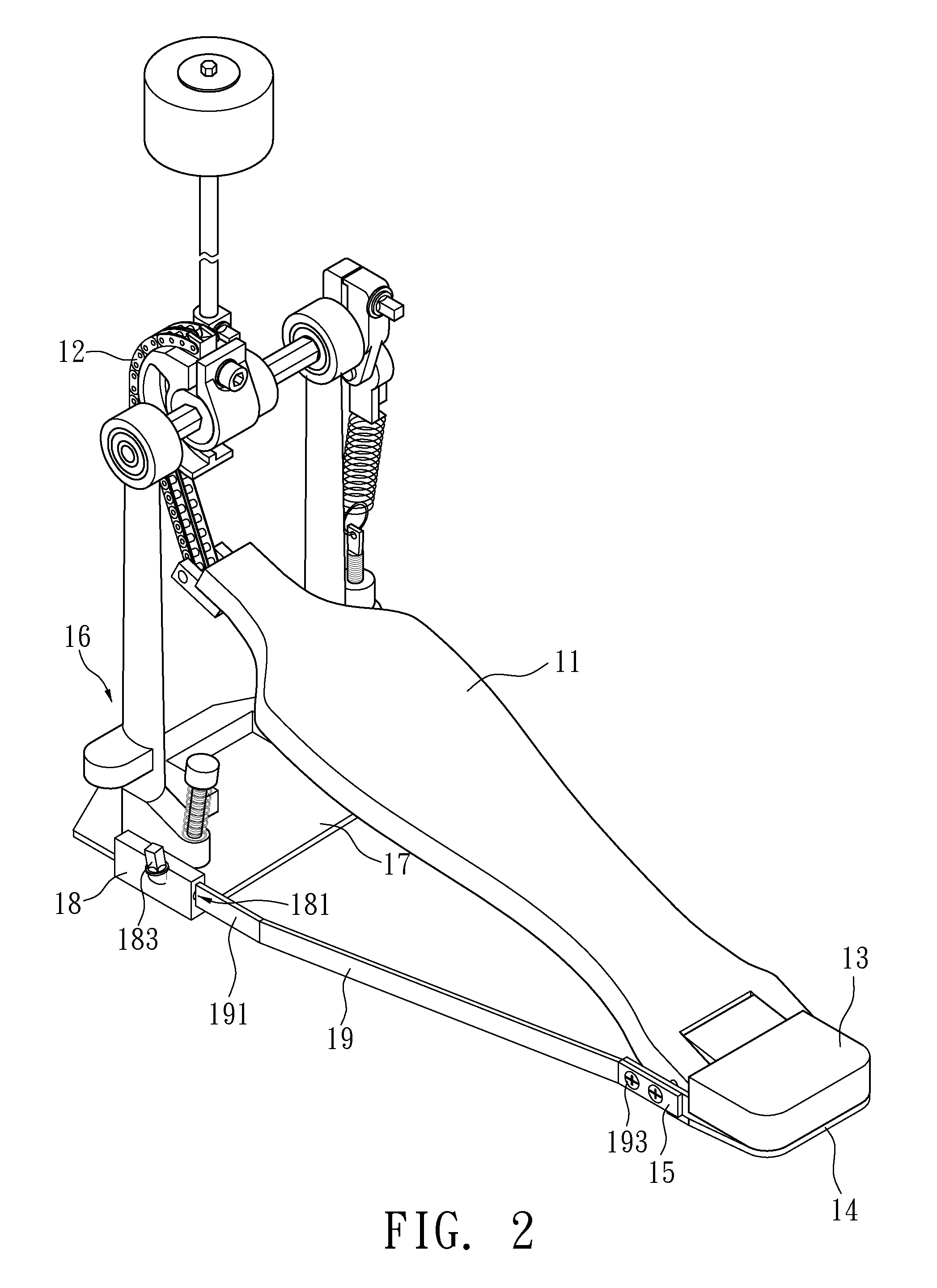
[0027]Referring to FIGS. 1 and 2, which show the first embodiment of the pedal assembly of the present invention and comprises a pedal 11 having a front end 111 thereof connected with a first end of a chain 12 and a rear end 112 of the pedal 11 is connected to a heel plate 13. The pedal 11 is pivotable at the rear end 112 thereof when the user steps on the pedal 11. A rear board 14 is connected to an underside of the heel plate 13. The rear board 14 includes multiple first holes 141 and screws 193 extend through the first holes 141 so as to connect the rear board 14 to the heel plate 13. In this embodiment, the screws 142 have a flat head. Two connection portions 15 are located on two sides of the rear board 14 and each connection portion 15 has multiple locking holes 151, in this embodiment, there are two locking holes 151 in each connection portion 15.

[0028]A base 16 has two posts 161 extending upward from two ends thereof and a shaft 162 is connected between the two posts 161. A ...

Example

[0037]FIGS. 8 and 9 show the second embodiment of the pedal assembly of the present invention which comprises a pedal 11 having a front end 111 thereof connected with a first end of a chain 12 and a rear end 112 of the pedal 11 is connected to a heel plate 13 which includes multiple positioning holes 131. In this embodiment, there are two positioning holes 131. The pedal 11 is pivotable at the rear end 112 thereof.

[0038]A base 16 has two posts 161 extending upward from two ends thereof and a shaft 162 is connected between the two posts 161. A locking member 163 is connected to the shaft 162 and a beater connection portion 164 is connected to the locking member 163. A second end of the chain 12 is connected to the locking member 163.

[0039]A front board 17 id located beneath the base 16 and the front board 17 includes multiple second holes 171, multiple screws 172 extend through the second holes 171 and are connected to an underside of the base 16. The screws 172 have a flat head. An ...


PUM


Abstract

A pedal assembly includes a pedal, a base and two frames, a chain is connected between the front end of the pedal and a locking member on the shaft of the base. The rear end of the pedal is pivotably connected to the heel plate so that the pedal is pivotable along the stepping direction. The heel plate and the base are positioned by the respective frames which are fixed to the base and the heel plate by screws. By using the screws, the pedal assembly is stable and made at less material. The frames can be adjusted back and forth to meet different users' needs such that the different sizes of the feet of the users can operate the pedal assembly efficiently.

Description

FIELD OF THE INVENTION[0001]The present invention relates to a pedal assembly, and more particularly, to a light and adjustable pedal assembly for percussion instrument.BACKGROUND OF THE INVENTION[0002]It is important for a band having tens of music instruments to have each of the instruments to be light and easily assembled.[0003]A conventional pedal assembly is shown in FIG. 10, and generally includes a base 71 and a heel plate 72 which is connected to a board 73. The user steps on the pedal 74 pivotably connected to the front end of the heel plate 72 and the pedal 74 is pivoted by the force that the user applies to the pedal 74.[0004]The conventional board 73 is usually heavy so that it is difficult to transport the pedal assembly. Besides, the conventional pedal assembly requires a lot of time to be assembled and dis-assembled. Also, the heavy board 73 needs too much material which means high cost.[0005]Furthermore, the pedal 74 needs to be adjusted according to the user's needs...

Claims


Application Information

Patent Timeline
IPC IPC(8): G10D13/02
CPCG10D13/006G10D13/11
Inventor LIN, HSI-TAN
Owner LIN HSI TAN
Why Eureka
Try Eureka