Device for reducing harmonics in three-phase poly-wire power lines

a technology of poly-wire power lines and harmonic reduction devices, which is applied in the direction of reducing harmonics/ripples in the ac network, instruments, process and machine control, etc., can solve the problems of reducing the harmonics component, reducing the power factor, and reducing the output of the electric generator or transformer, so as to reduce the harmonics. the effect of most components

Inactive Publication Date: 2009-12-08
LEE SUNG HO
View PDF9 Cites 32 Cited by
  • Summary
  • Abstract
  • Description
  • Claims
  • Application Information

AI Technical Summary

Benefits of technology

[0012]The invention provides a harmonics reduction device which removes zero-phase harmonics current by using a zigzag transformer, and offsets most of the harmonics current introduced into an electric power system via a neutral line at a load side by using an open delta connection portion which open-delta-connects the neutral lines of the electric power system and the load side, to thus reduce most of harmonics components introduced into the electric power system without causing disconnection or cut of the neutral line.

Problems solved by technology

As electric devices are being recently increasingly used, harmonics current generated at the load sides are flown into an electric power system via a neutral line, to thereby cause lowering of the output, burning of coils, lowering of a power factor, and a power loss of an electric generator or transformer.
However, the reactors may be overheated by loads such as direct-current equipment, high-speed electric railways, mercury discharging lamps, star-connection wired transformers which generate much harmonics current and thus wires are frequently disconnected or cut.
And the harmonics reduction effect by the reactors may be badly fluctuated and the wires would be cut owing to the overdue earth fault current.
Accordingly, the neutral line may be disconnected or cut, to accordingly cause problems that the voltage at the load side is not balanced, and the maximum two-times voltage is applied to the load.

Method used


Image

  • Device for reducing harmonics in three-phase poly-wire power lines
  • Device for reducing harmonics in three-phase poly-wire power lines
  • Device for reducing harmonics in three-phase poly-wire power lines

Examples


Embodiment Construction

[0023]Hereinbelow, a harmonics reduction device in three-phase poly-wire power lines according to the present invention will be described with reference to the accompanying drawings.

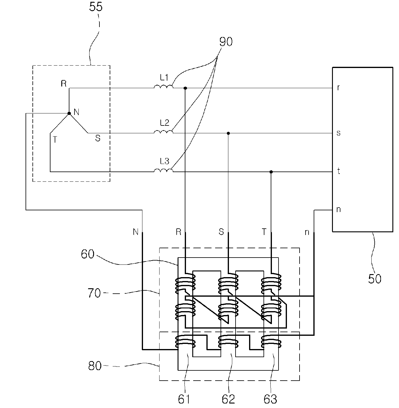
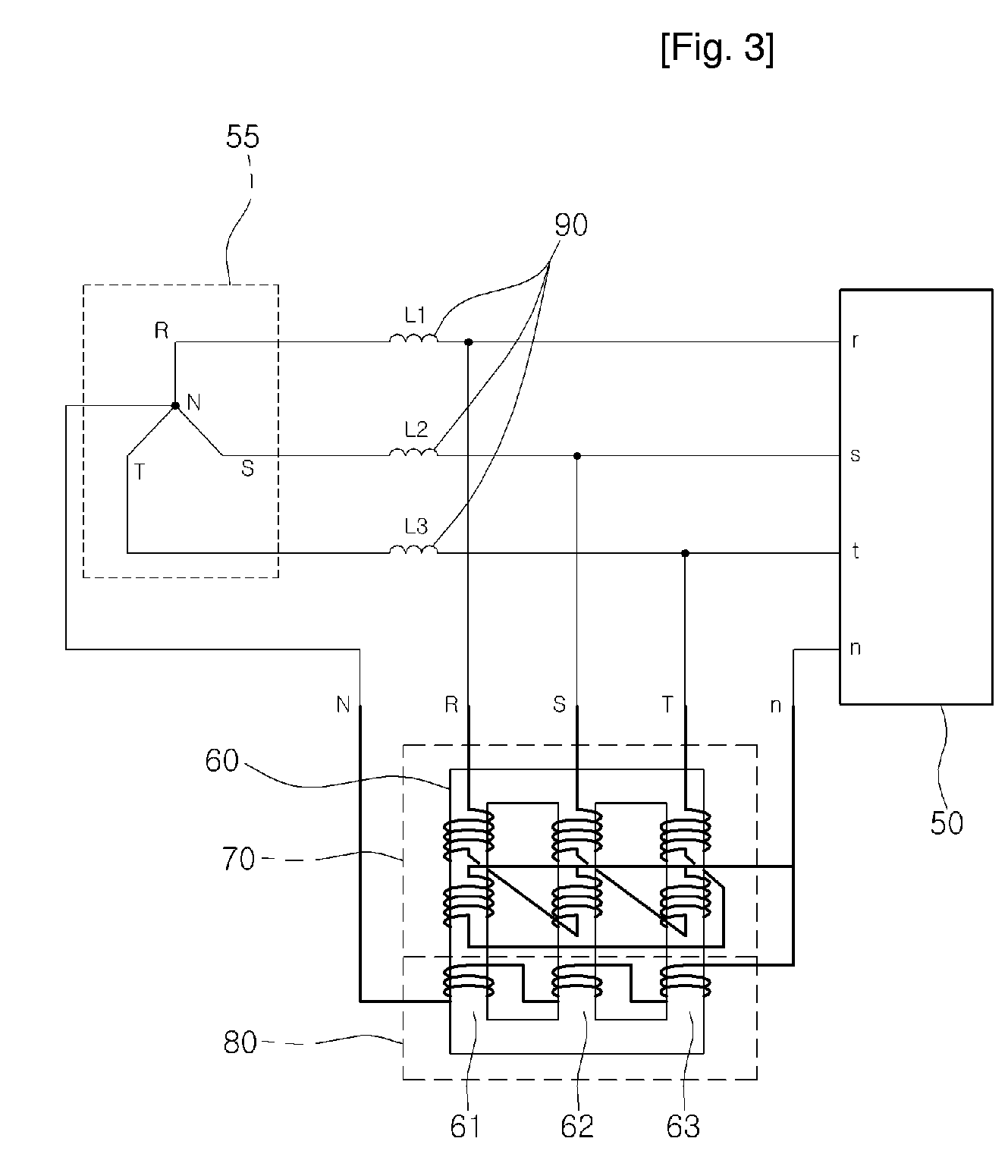
[0024]FIG. 3 is a circuitry diagram showing a harmonics reduction device according to an embodiment of the present invention.

[0025]Referring to FIG. 3, a harmonics reduction device in three-phase poly-wire power lines according to the present invention includes a zigzag transformer 70 in which windings connected between an electric power system 55 and a load 50 are wound through a core 60 having three legs 61, 62 and 63, respectively, in a zigzag form, and an open delta connection portion 80 in which an winding is wound through the three legs 61, 62 and 63 between a neutral line of the electric power system 55 and that of the load 50. Here, the open delta connection is a connection in which one connecting point among the three connecting points of three phase delta connection is opened.

[0026]Preferably, ...


PUM

PropertyMeasurementUnit
voltageaaaaaaaaaa
magnetic fluxaaaaaaaaaa
power factoraaaaaaaaaa

Abstract

The invention is a harmonics reduction device for three-phase poly-wire power lines, which can more reliably eradiate harmonics current applied to an electric power system via a neutral line. The invention comprises an electric power system having three-phase poly-wire power lines in order to supply alternating-current (AC) power voltage to a load; a zigzag transformer in which windings connected with three-phase lines in the electric power system are wound through first and second legs, second and third legs, and third and first legs of a core having three legs, respectively, while varying direction of each magnetic flux, and an intermediate point of each winding is commonly connected with a neutral line of the electric power system and that of the load; and an open delta connection portion in which an winding connected with the neutral line of a load side is wound through the three legs so as to be connected with a neutral line of the electric power system.

Description

TECHNICAL FIELD[0001]The present invention relates to a device for reducing harmonics in three-phase poly-wire power lines, and more particularly to, a harmonics reduction device for three-phase poly-wire power lines, which can more reliably eradiate harmonics current applied to an electric power system via a neutral line.BACKGROUND ART[0002]As electric devices are being recently increasingly used, harmonics current generated at the load sides are flown into an electric power system via a neutral line, to thereby cause lowering of the output, burning of coils, lowering of a power factor, and a power loss of an electric generator or transformer. Thus, a device for reducing harmonics current should be necessarily installed in the electric power lines.[0003]Most of the conventional harmonics reduction methods are performed by employing reactors installed between a neutral line of an electric power system and that of each load side, in order to reduce harmonics waves. However, the react...

Claims


Application Information

Patent Timeline
Patent Type & Authority Patents(United States)
IPC IPC(8): H01F30/12G05F1/12H02H7/04H02J1/02
CPCH02J3/01H01F30/12H01F27/385Y02E40/40
Inventor LEE, SUNG HO
Owner LEE SUNG HO
Why Eureka
Try Eureka