Multifunctional radio frequency directed energy system

a radio frequency directed energy and multi-functional technology, applied in communication jamming, instruments, measurement devices, etc., can solve the problems of add-on systems adding significant cost and complexity to the rfde system, add-on systems adding significant complexity, and add-on systems significantly increasing the cost and complexity of the rfde system, so as to achieve the effect of substantially reducing the cost of the overall system

Inactive Publication Date: 2009-12-08
RAYTHEON CO
View PDF61 Cites 21 Cited by
  • Summary
  • Abstract
  • Description
  • Claims
  • Application Information

AI Technical Summary

Benefits of technology

[0009]The RFDE system of the present invention eliminates the need for a separate, stand-alone targeting system by integrating a targeting system within the RFDE system itself. The RFDE system is multi-functional in that all or part of the RFDE system hardware that functions to direct high power electromagnetic energy also functions to obtain and provide targeting information to aim the high power electromagnetic energy beam. For example, the RFDE transmitter is not only used as the source of the directed electromagnetic energy, but is also used as a radar transmitter for targeting an object. A relatively simple radar receiver may then be added to the RFDE system. The cost of the overall system is substantially reduced since an expensive radar transmitter is not required.
[0010]Moreover, the complexity of the system is reduced as calibration of the alignment between the RFDE system and a stand-alone targeting system becomes unnecessary.

Problems solved by technology

An ongoing problem with RFDE systems is targeting—accurately pointing the RF directed energy beam at the intended target and establishing an accurate range from the system to the target.
However, these add-on systems add significant cost to the RFDE system.
In addition, these add-on systems add significant complexity by requiring calibration of the alignment between the RFDE system and the stand-alone targeting system.
As is also noted above, however, these add-on systems add significantly to the cost and complexity of the RFDE system.

Method used


Image

  • Multifunctional radio frequency directed energy system
  • Multifunctional radio frequency directed energy system
  • Multifunctional radio frequency directed energy system

Examples


Embodiment Construction

[0023]The present invention will now be described with reference to the drawings, in which like reference numerals are provided to refer to like elements throughout.

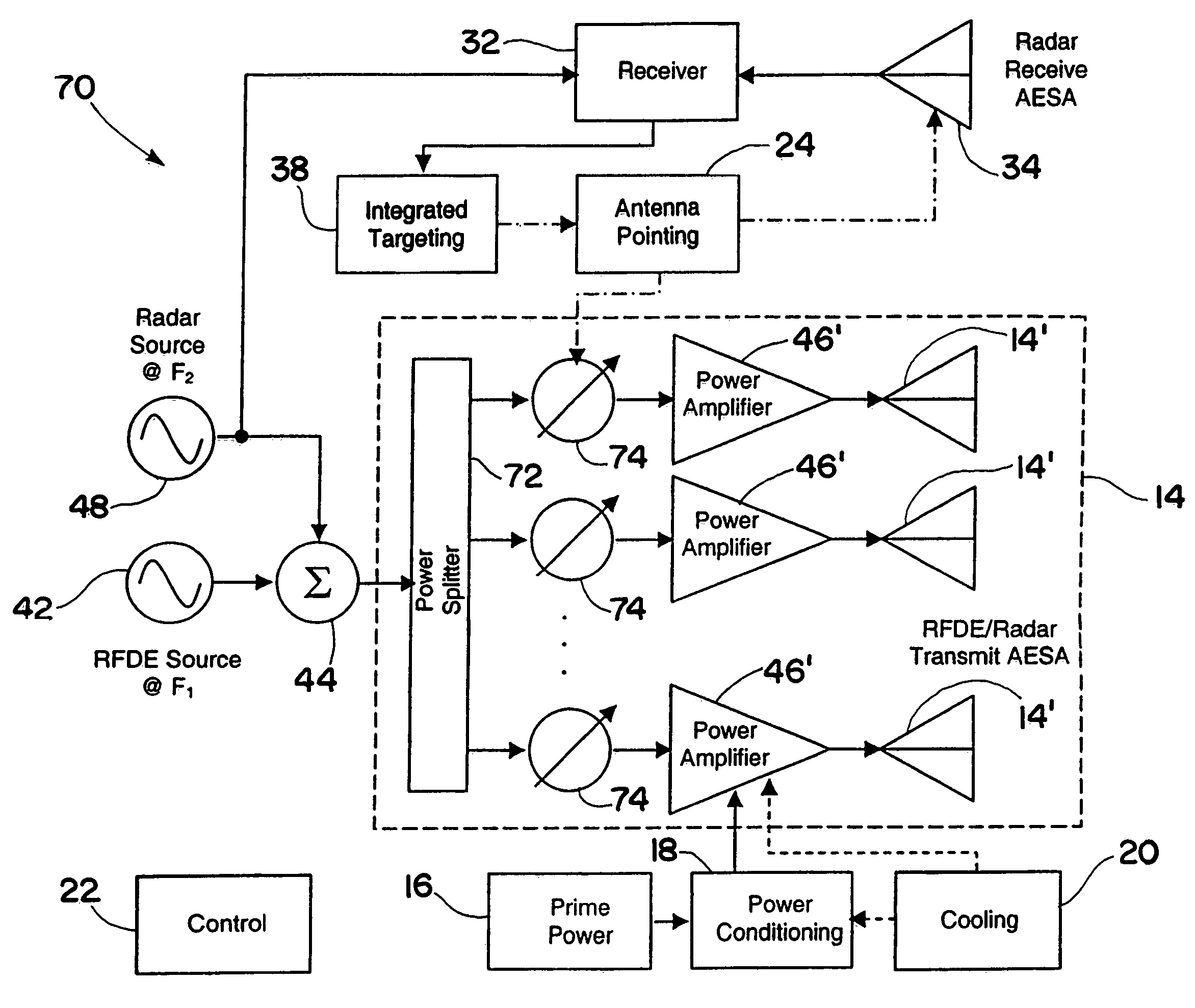
[0024]The RFDE system of the present invention integrates a targeting system, such as a radar targeting, system, into an otherwise conventional RFDE system. There are several ways that the targeting system can be integrated into the RFDE system as explained herein. The particular embodiments described below are meant to be merely exemplary. The present invention contemplates not only the particular embodiments described herein, but any system in which a targeting system is integrated in part or in whole within the RFDE system.

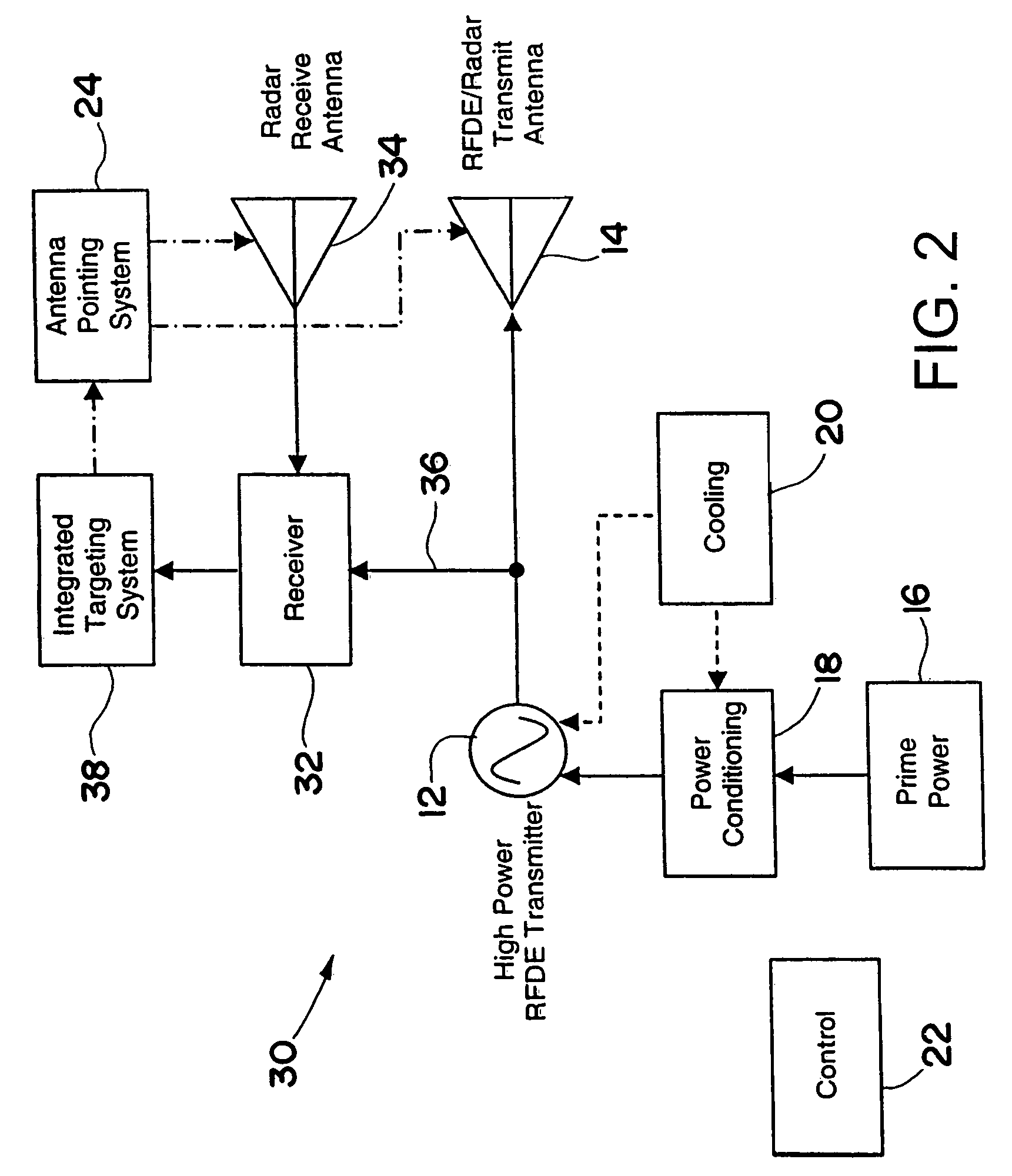
[0025]Referring to FIG. 2, an RFDE system 30 is shown in accordance with an embodiment of the present invention. Since many of the elements of the RFDE system 30 in FIG. 3 are similar to those in the conventional system 10 discussed above with respect to FIG. 1, only the relevant differences with be...


PUM


Abstract

An RFDE system includes an RFDE transmitter and at least one RFDE antenna. The RFDE transmitter and antenna direct high power electromagnetic energy towards a target sufficient to cause high energy damage or disruption of the target. The RFDE system further includes a targeting system for locating the target. The targeting system includes a radar transmitter and at least one radar antenna for transmitting and receiving electromagnetic energy to locate the target. The RFDE system also includes an antenna pointing system for aiming the at least one RFDE antenna at the target based on the location of the target as ascertained by the targeting system. Moreover, at least a portion of the radar transmitter or the at least one radar antenna is integrated within at least a portion of the RFDE transmitter or the at least one RFDE antenna.

Description

TECHNICAL FIELD[0001]The present invention relates generally to radio frequency directed energy (RFDE) systems, and more particularly to multifunctional type RFDE systems.BACKGROUND OF THE INVENTION[0002]Radio frequency directed energy (RFDE) systems are known in the art for directing high power RF, microwave and / or millimeter wave electromagnetic energy to destroy or disrupt a target. Although RFDE systems typically serve as military weapons, RFDE systems need not be limited to weapon systems. For example, RFDE systems of the present invention may be used for non-military purposes such as destroying or disrupting foreign objects, contaminants, undesirable atmospheric conditions, or other types of targets.[0003]As for weapon systems, it is important to distinguish between an RFDE weapon system and an electronic warfare system. A primary difference between an RFDE weapon and an electronic warfare system is power and kill mode. An electronic warfare system makes use of a priori knowle...

Claims


Application Information

Patent Timeline
Patent Type & Authority Patents(United States)
IPC IPC(8): G01S13/66G01S7/38
CPCF41H13/0043G01S7/38H04K3/45H04K3/62G01S7/024H04K2203/32G01S2013/0272
Inventor BROWN, KENNETH W.CANICH, DAVID J.BERG, RUSSELL F.
Owner RAYTHEON CO
Why Eureka
Try Eureka