Color image forming apparatus

a color image and forming apparatus technology, applied in the field of color image forming apparatus, can solve the problems of long image forming time, difficult to obtain a high-quality full-color image, high cost, etc., and achieve the effect of reducing color discrepancy, high-quality color image, and large increase in cos

Inactive Publication Date: 2009-12-08
CANON KK
View PDF19 Cites 19 Cited by
  • Summary
  • Abstract
  • Description
  • Claims
  • Application Information

AI Technical Summary

Benefits of technology

[0010]In view of the above problems in the conventional art, the present invention has an object to provide a color image forming apparatus which can obtain a high-quality color image by reducing color discrepancy without large increase in cost.

Problems solved by technology

However, this method must repeat three (four if black is used) image forming processes to obtain a print image on one sheet, resulting in a long image forming time.
On the other hand, a color discrepancy program has occurred due to misalignments of respective colors on a transfer material resulting from errors of the positional precisions and diameters of photosensitive members, and the positional precision errors of optical systems, and it is difficult to obtain a high-quality full-color image.
First, in order to correct the optical path of the optical system, a correction optical system including a light source and f-θ lens, a mirror in the optical path, and the like must be mechanically moved to adjust the position of the test toner image. For this purpose, high-precision movable members are required, resulting in high cost. Furthermore, since it takes much time until correction is completed, it is impossible to frequently perform correction. However, an optical path length difference may change along with an elapse of time due to temperature rise of mechanical components. In such case, it becomes difficult to prevent color discrepancy by correcting the optical path of the optical system.
Second, in order to correct the image write start position, it is possible to conduct misalignment correction of the left end and upper left portion but it is impossible to correct the tilt of the optical system and to correct any magnification errors due to the optical path length difference.
For this reason, the calculation volume becomes large, and the arrangement of a processing system becomes complicated.

Method used


Image

  • Color image forming apparatus
  • Color image forming apparatus
  • Color image forming apparatus

Examples


first embodiment

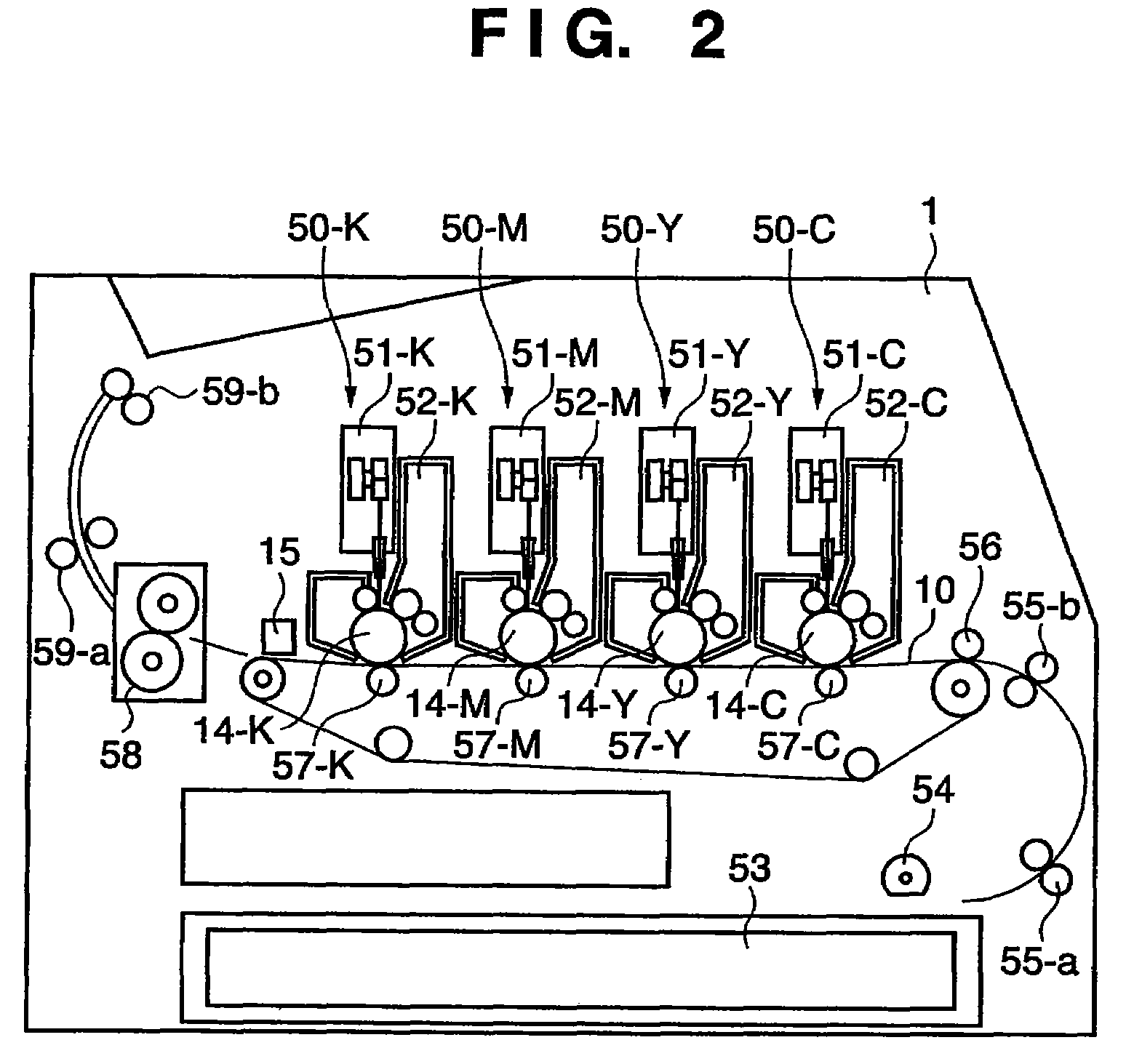
[0056]FIG. 2 is a schematic sectional view showing the arrangement of a color image forming apparatus according to this embodiment. A color image forming apparatus 1 shown in FIG. 2 is a color laser beam printer of a so-called tandem system, which comprises, e.g., four photosensitive drums. This color image forming apparatus 1 mounts a transfer material cassette 53 in a lower portion of the right side surface of its main body. Transfer materials set in the transfer material cassette 53 are picked up one by one by a paper feed roller 54, and each transfer material is fed to image forming units by guide roller pairs 55-a and 55-b. A feeding belt 10 that feeds the transfer material is stretched flat via a plurality of rotary rollers in the transfer material feeding direction (from the right to the left in FIG. 2), and the transfer material is electrostatically attracted on the most upstream portion of the feeding belt 10.

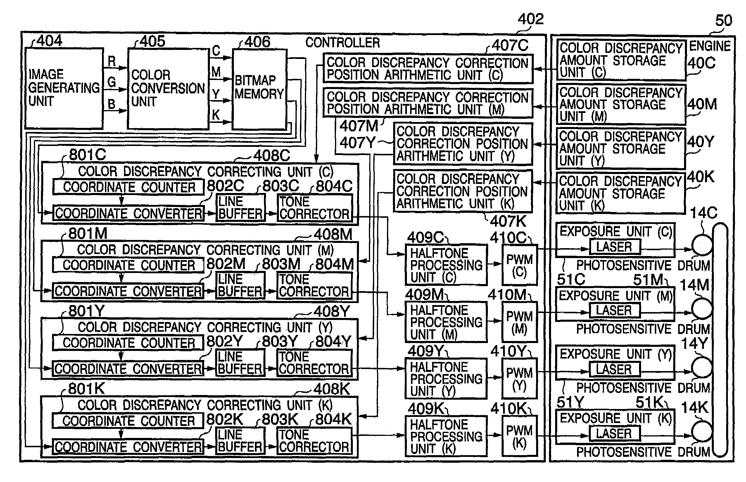
[0057]The color image forming apparatus 1 has four image forming ...

second embodiment

[0133]In the second embodiment, when the density of the tone correction is switched at, e.g., three pixels in four levels, it is done at (a) a position where coordinate conversion is performed, (b) a position one pixel before the position where coordinate conversion is performed, and (c) a position two pixels before the position where coordinate conversion is performed.

[0134]Hence, the color discrepancy correction position arithmetic units 407C, 407M, 407Y, and 407K respectively calculate the position one pixel before the position where coordinate conversion is performed, and the position two pixels before the position where coordinate conversion is performed.

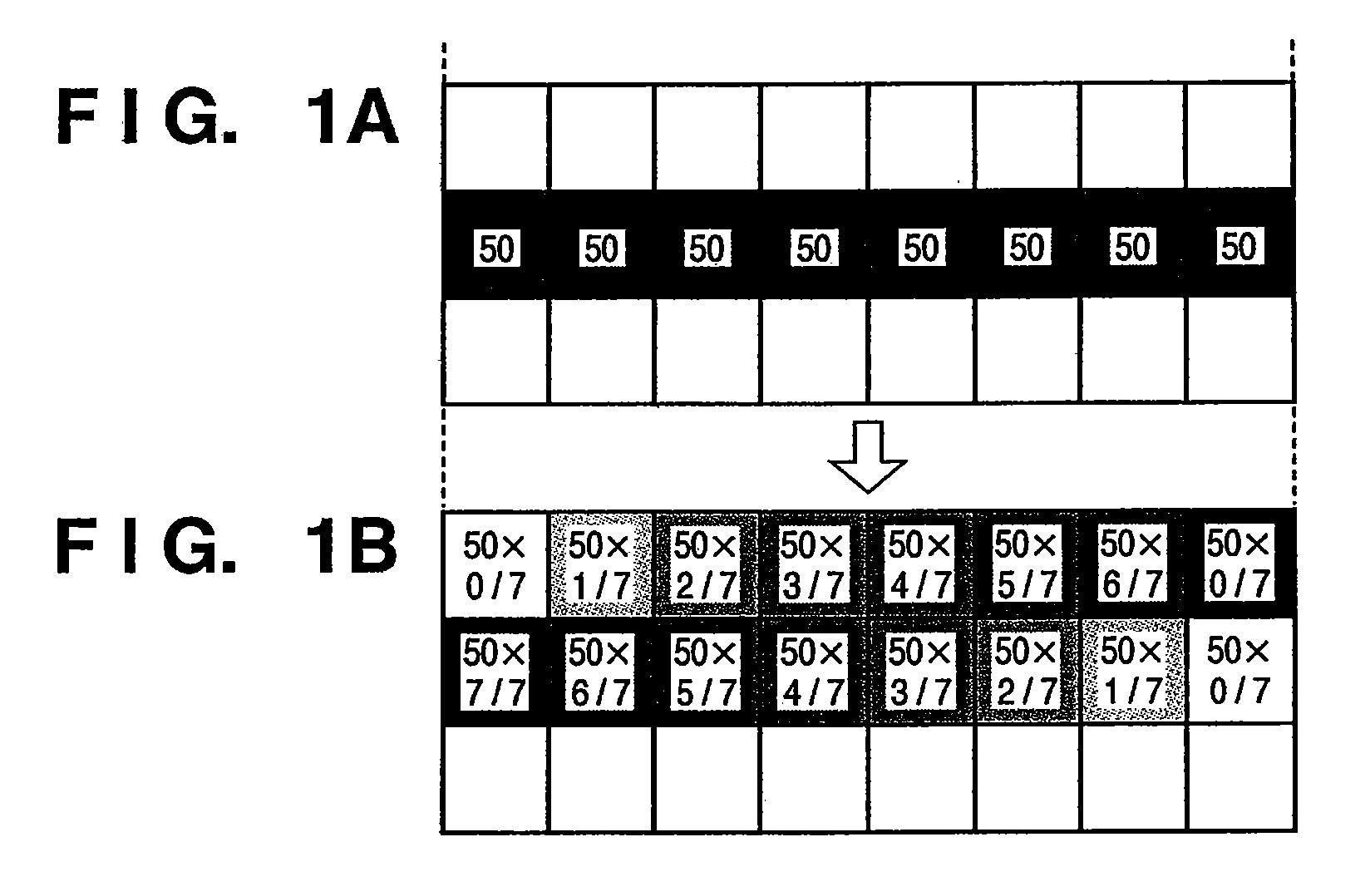
[0135]FIGS. 9A to 9G are views for explaining color discrepancy correction in less than the pixel unit by the tone corrector 804. The discrepancy amount correction in less than the pixel unit is implemented by adjusting the exposure ratios of neighboring dots in the sub-scan direction.

[0136]FIG. 9A shows an image of a main scan...

third embodiment

[0170]According to parent reference 2 (Japanese Patent Application Laid-Open No. 8-85237) described above, the output coordinate position of image data for each color is corrected for an image that has undergone halftone processing. For this reason, if dithering is applied, reproducibility of halftone dots of a halftone image deteriorates. As a result, color inconsistency may occur and moiré may become obvious. Furthermore, when such non-uniform density values are periodically repeated, moiré becomes obvious, and a high-quality color image cannot be obtained. The third embodiment solves such drawbacks.

[0171]A color image forming apparatus according to the embodiment of the present invention is also a four-drum color laser beam printer, and FIG. 2 will be quoted.

[0172]FIG. 10 is a conceptual view for explaining a misalignment of a main scan line scanned on each photosensitive drum 14 as an image carrier (for example, the photosensitive drum 14-C for cyan). Since the same applies to p...


PUM

PropertyMeasurementUnit
photosensitiveaaaaaaaaaa
color discrepancyaaaaaaaaaa
densityaaaaaaaaaa

Abstract

A color image forming apparatus of a so-called tandem type which has image forming units in correspondence with colors is provided. In the color image forming apparatus, a color discrepancy amount storage unit stores information of a color discrepancy amount of each of the image forming units, which is measured in advance. A first color discrepancy correcting unit performs color discrepancy correction in a pixel unit by performing coordinate conversion of bitmap data to be printed based on the information of the color discrepancy amount stored in the color discrepancy amount storage unit. A second color discrepancy correcting unit performs color discrepancy correction in less than a pixel unit by performing tone correction of the bitmap data corrected by the first color discrepancy correcting unit based on the information of the color discrepancy amount stored in the color discrepancy amount storage unit.

Description

FIELD OF THE INVENTION[0001]The present invention relates to a color image forming apparatus and, more particularly, to a color image forming apparatus of an electrophotographic method.BACKGROUND OF THE INVENTION[0002]A color image forming apparatus of an electrophotographic method is well known. In this method, one photosensitive member undergoes developments of respective colors using a plurality of developers, color images are superposed and formed on a single transfer material by repeating exposure, development, and transfer processes a plurality of number of times, and these color images are fixed to obtain a full-color image.[0003]However, this method must repeat three (four if black is used) image forming processes to obtain a print image on one sheet, resulting in a long image forming time.[0004]As a system that can cope with this drawback, a so-called tandem system which superposes visual images obtained for respective colors using a plurality of photosensitive members to o...

Claims


Application Information

Patent Timeline
Patent Type & Authority Patents(United States)
IPC IPC(8): H04N1/409B41J2/435B41J2/47G03F3/08G03G15/01G06K1/00G06K9/00
CPCH04N1/506H04N2201/04787G03G15/00G03G15/01
Inventor TOJIMA, KENZOKITAMURA, HIROKIAKIBA, YOSHIYUKITAKATA, TSUTOMUNAKAMURA, SHUICHIYAMAMOTO, YUSUKEMOTOYAMA, MASANAOAKIYAMA, TAKESHINAGAOKA, TAKAAKI
Owner CANON KK
Why Eureka
Try Eureka