Light emitting device

a technology of light-emitting devices and light-emitting components, which is applied in the direction of semiconductor devices, electrical devices, disassembly and assembly of devices, etc., can solve the problems of not having a sufficient emission intensity in the blue green region and the red region, and achieve the effect of high-quality color rendering properties

Active Publication Date: 2020-09-08
NICHIA CORP
View PDF28 Cites 0 Cited by
  • Summary
  • Abstract
  • Description
  • Claims
  • Application Information

AI Technical Summary

Benefits of technology

[0008]Given the situation, one embodiment of the present invention is to provide a light emitting device having a sterilization effect and having a high-quality color rendering property for comfortable use even in human visual environments.
[0013]According to the present disclosure, there can be provided a light emitting device having a sterilization effect and having a high-quality color rendering property for comfortable use even in human visual environments.

Problems solved by technology

Such a light emitting device may have a strong emission intensity in a human visible light range of 380 nm to 780 nm and have a high emission efficiency, but could not have a sufficient emission intensity in a blue green region and a red region as the case may be.
However, in the case where a light emitting element capable of emitting a light falling within a wavelength range of 380 nm to 420 nm that has a sterilization effect is used, the emission intensity in a violet region is large, as compared with a light emitting element having an emission peak wavelength at around 450 nm and used, for example, in a light emitting device that emits a white mixed color light, and accordingly, the case could not provide a sufficient emission intensity in a blue region and further improvement for the color rendering property is needed.

Method used


Image

  • Light emitting device
  • Light emitting device
  • Light emitting device

Examples


example 1

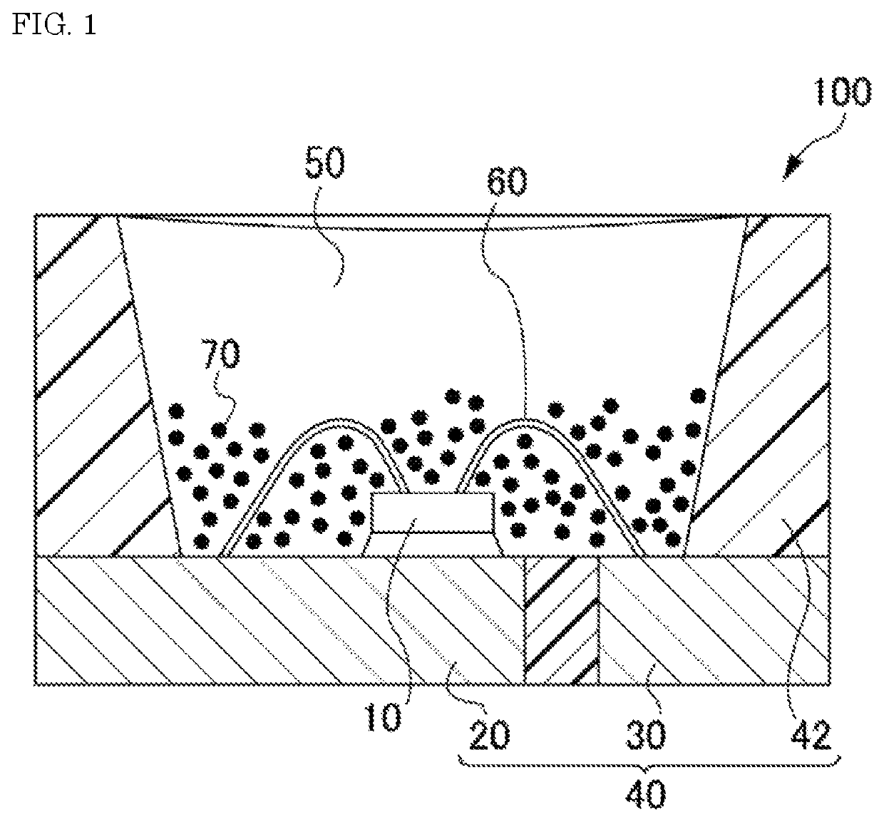
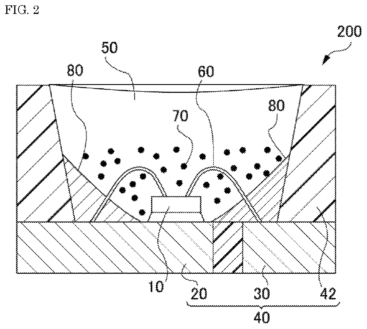
[0090]In the light emitting device 200, a light emitting element 10 having an emission peak wavelength of 405 nm was used. A silicone resin was used as the sealing material to constitute the fluorescent member 50. A fluorescent material containing a halogen-containing alkaline earth metal phosphate was used as the first fluorescent material, a fluorescent material containing a rare earth aluminate was used as the second fluorescent material, and a fluorescent material containing a nitride was used as the third fluorescent material. The first fluorescent material, the second fluorescent material and the third fluorescent material used in Examples and Comparative Examples are shown in Table 1. The first fluorescent material, the second fluorescent material and the third fluorescent material were so blended that the correlated color temperature of the mixed light of the light from the light emitting element 10 and the light from the fluorescent material 70 containing the first fluoresc...

examples 2 to 10

[0091]Light emitting devices of Examples 2 to 10 were produced in the same manner as in Example 1, except that the kind of the first fluorescent material, the second fluorescent material and the third fluorescent material and the content of each fluorescent material relative to the total mass of the fluorescent materials were changed as in Table 2 and the first fluorescent material, the second fluorescent material and the third fluorescent materials were blended.

example 11

[0109]A light emitting device of Example 11 was produced in the same manner as in Example 1, except that the kind of the first fluorescent material, the second fluorescent material and the third fluorescent material and the content of each fluorescent material relative to the total mass of the fluorescent materials were changed as in Table 4 and the first fluorescent material, the second fluorescent material and the third fluorescent material were blended in such a manner that the correlated color temperature of the mixed light of the light from the light emitting element 10 and the light from the fluorescent material 70 containing the first fluorescent material, the second fluorescent material and the third fluorescent material could be around 4000 K.


PUM

PropertyMeasurementUnit
emission peak wavelengthaaaaaaaaaa
color temperatureaaaaaaaaaa
wavelength rangeaaaaaaaaaa

Abstract

A light emitting device includes a light emitting element having an emission peak wavelength in a range of 380 nm to 420 nm and a fluorescent member including at least one fluorescent material that is excited by light from the light emitting element for light emission, wherein a mixture of light from the light emitting element and light from the fluorescent material has a correlated color temperature in a range of 2000 K to 7500 K as measured according to JIS Z8725, and the light emitting device has a spectral distribution in which, when the integral value over a wavelength range of 380 nm to 780 nm is normalized to 100%, the proportion of an integral value over a wavelength range of 380 nm to 420 nm is 15% or more, and the ratio a as defined by the expression (1) is 0.9 or more and 1.6 or less.

Description

CROSS-REFERENCE TO RELATED PATENT APPLICATION[0001]This application claims priority to Japanese Patent Application No. 2018-105560, filed on May 31, 2018, and Japanese Patent Application No. 2019-95441, filed on May 21, 2019, the entire disclosures of which are incorporated herein by references in their entirety.BACKGROUNDTechnical Field[0002]The present invention relates to a light emitting device.Description of Related Art[0003]A light emitting device is known that uses, as a light emitting element such as a light emitting diode (hereinafter this may also be referred to as “LED”), a light emitting element that emits a blue color, and uses a fluorescent material that emits a yellow color as excited by the light from the light emitting element, emitting a white mixed color light. Such a light emitting device may have a strong emission intensity in a human visible light range of 380 nm to 780 nm and have a high emission efficiency, but could not have a sufficient emission intensity i...

Claims


Application Information

Patent Timeline
Patent Type & Authority Patents(United States)
IPC IPC(8): H01L33/50H01L33/60H01L33/56A61L2/08H01L33/48H01L33/62H01L33/32
CPCH01L33/60H01L33/56A61L2/084H01L33/507H01L33/504H01L33/62H01L33/32H01L33/486A61L2202/11H01L33/48H01L33/502A61L2/08
Inventor IWASA, MAKIKOFUJIO, KAZUSHIGE
Owner NICHIA CORP
Why Eureka
Try Eureka