
Wheeled attachment system

a technology of attachment system and wheel, which is applied in the field of wheeled attachment system, can solve the problems of not being efficiently maneuverable among stairs, hazardous for the patient along with the individual carrying the board, etc., and achieve the effect of convenient attachment and detachment, smooth down or down

Inactive Publication Date: 2009-12-15
LARSON DONALD O
View PDF14 Cites 36 Cited by
  • Summary
  • Abstract
  • Description
  • Claims
  • Application Information

AI Technical Summary

Benefits of technology

[0013]An object is to provide a wheeled attachment system for efficiently attaching to a spine board to allow the spine board to be easily maneuvered over various surfaces (e.g. flat surfaces, stairs, etc.).
[0015]A further object is to provide a wheeled attachment system that includes a tri-wheeled structure to allow the attached spine board to be smoothly maneuvered down or up a flight of stairs.
[0016]A further object is to provide a wheeled attachment system that may easily attach and detach from a spine board via a strap.

Problems solved by technology

This can be hazardous for the patient along with the individual carrying the board.
Attempts have been made to attach wheels to an end of the board; however while the wheels may provide easy transportation among flat surfaces they generally are not efficiently maneuverable among stairs.

Method used


Image

  • Wheeled attachment system
  • Wheeled attachment system
  • Wheeled attachment system

Examples


Embodiment Construction

A. Overview

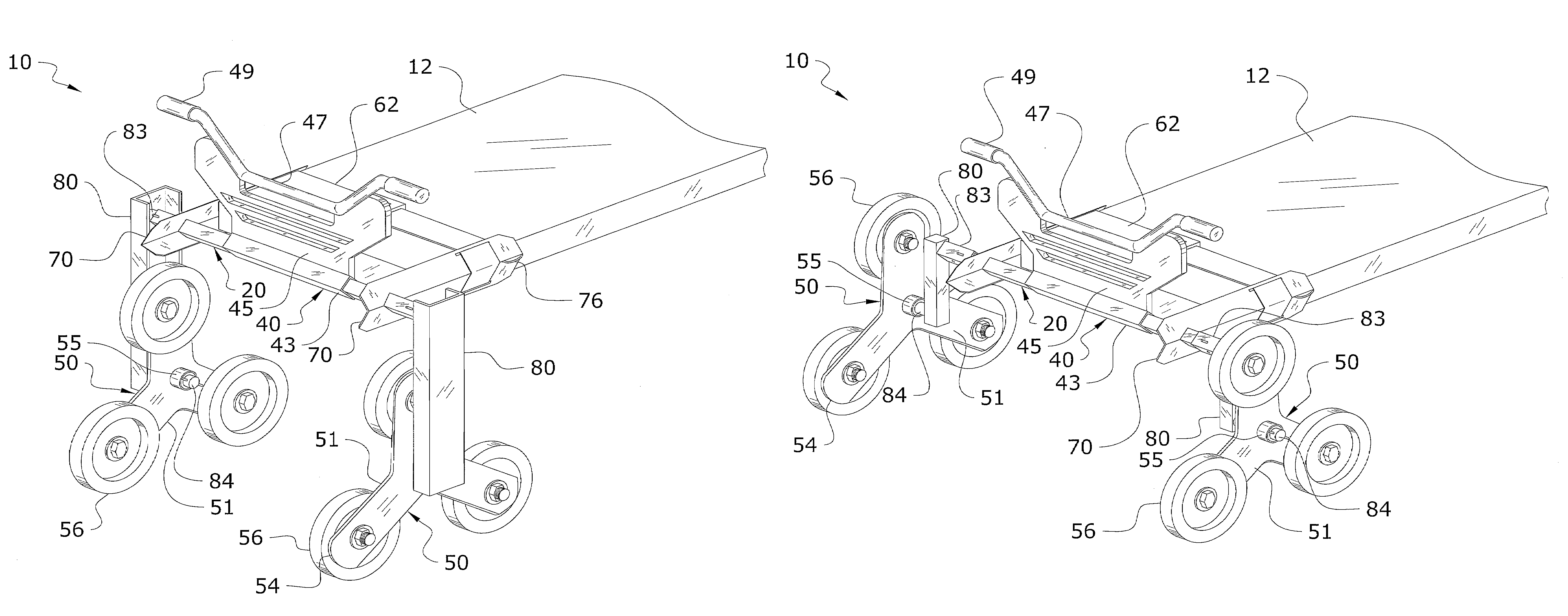
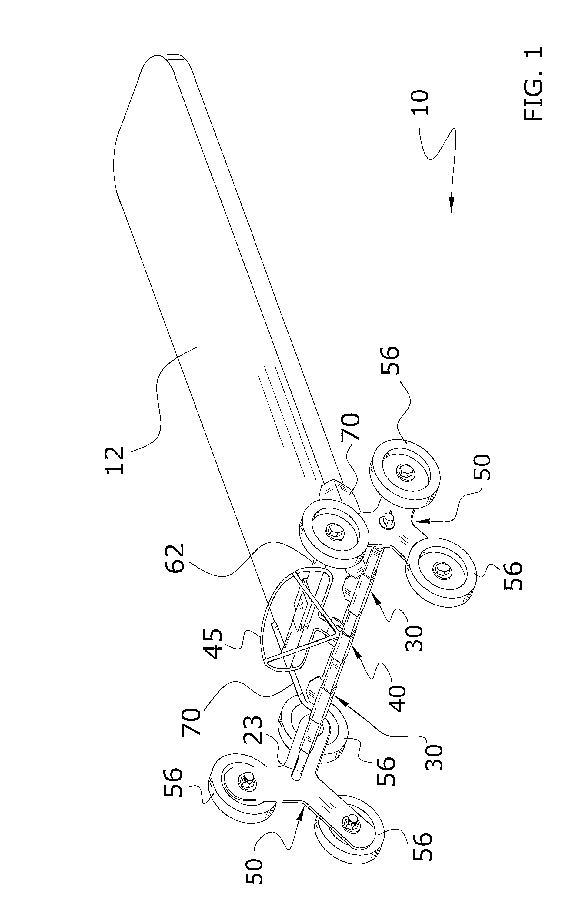
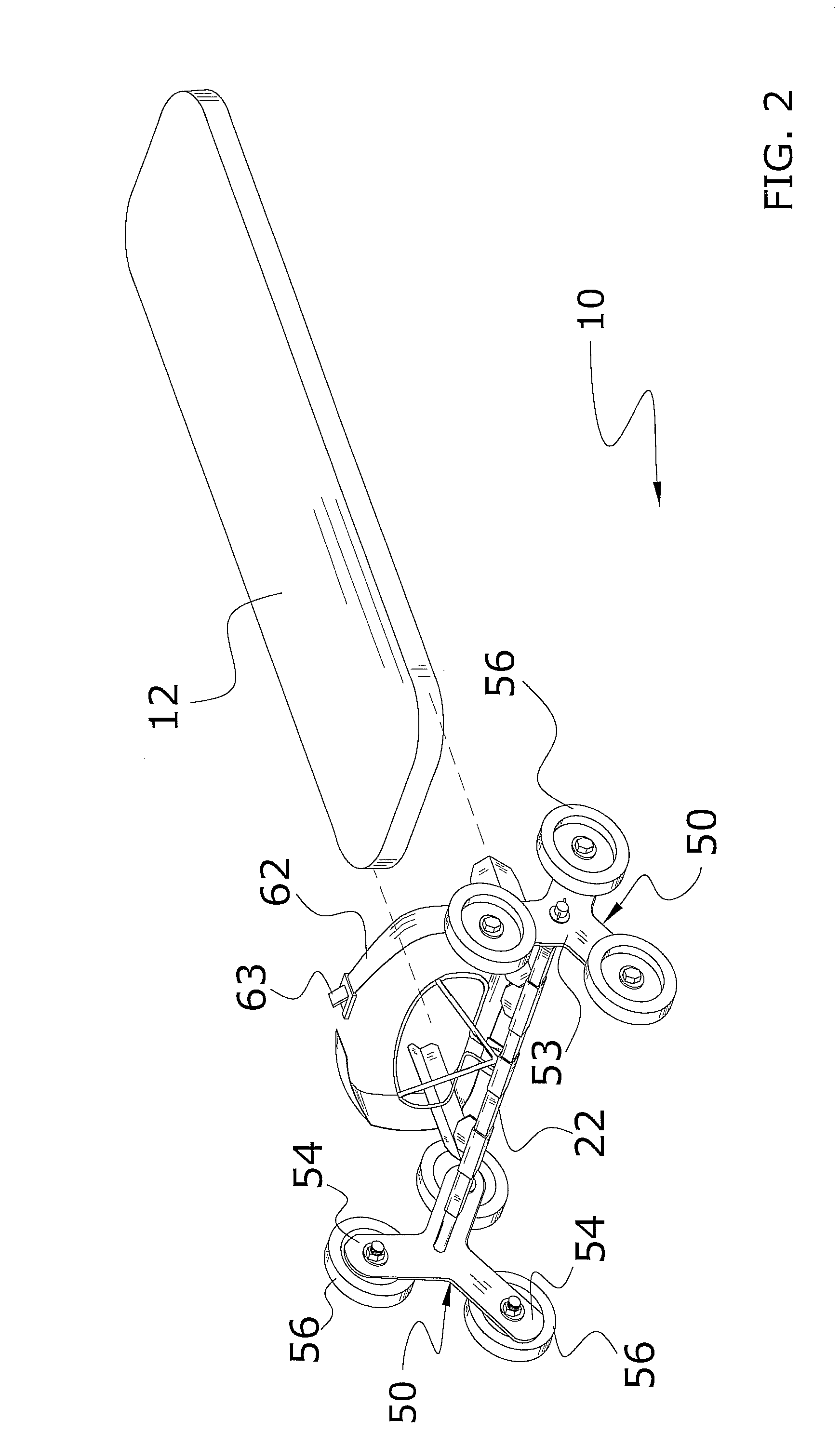
[0038]Turning now descriptively to the drawings, in which similar reference characters denote similar elements throughout the several views, FIGS. 1 through 18 illustrate a wheeled attachment system 10, which comprises a front support 20 including a cross member 22, a plurality of wheels 56 and at least one support 30 and a foot rest assembly 40, wherein at least three of the plurality of wheels 56 are rotatably attached at each opposing end of the cross member 22 and wherein the plurality of wheels 56 form a tri-wheeled assembly upon each of the opposing ends of the cross member 22. The support 30 and foot rest assembly 40 extend outwardly from the cross member 22 between the opposing ends of the cross member 22, wherein the support 30 and foot rest assembly 40 stabilize the front support 20 upon an object 12 (e.g. spine board, etc.) positioned adjacent the front support 20. An attachment structure 60 extends from the front support 20, wherein the attachment structure 60...


PUM


Abstract

A wheeled attachment system for efficiently attaching to a spine board to allow the spine board to be easily maneuvered over various surfaces (e.g. flat surfaces, stairs, etc.). The wheeled attachment system generally includes a front support, a pair of wheel assemblies extending from opposing sides of the front support, a pair of side supports extending from the front support adjacent the pair of wheel assemblies and at least one strap extending from the pair of side supports. The side supports and the front support define a cavity adapted to receive an end of a spine board, wherein the strap is adapted to secure the pair of wheel assemblies about the spine board. A pair of extension members interconnect the pair of wheel assemblies with the front support so that a center rotational axis of the pair of wheel assemblies is vertically offset with the front support.

Description

CROSS REFERENCE TO RELATED APPLICATIONS[0001]I hereby claim benefit under Title 35, United States Code, Section 120 of U.S. Pat. No. 7,516,503 filed May 14, 2008 which claims benefit of U.S. Pat. No. 7,516,502 filed Sep. 10, 2007. This application is a continuation in-part of the Ser. No. 12 / 120,640 application now U.S. Pat. No. 7,516,503 which is a continuation in-part of the Ser. No. 11 / 852,793 application now U.S. Pat. No. 7,516,502. The U.S. Pat. Nos. 7,516,503 and 7,516,502 are hereby incorporated by reference into this application.STATEMENT REGARDING FEDERALLY SPONSORED RESEARCH OR DEVELOPMENT[0002]Not applicable to this application.BACKGROUND OF THE INVENTION[0003]1. Field of the Invention[0004]The present invention relates generally to spine boards and more specifically it relates to a wheeled attachment system for efficiently attaching to a spine board to allow the spine board to be easily maneuvered over various surfaces (e.g. flat surfaces, stairs, etc.).[0005]2. Descript...

Claims


Application Information

Patent Timeline
IPC IPC(8): A61G1/02A61G1/04B62B1/00
CPCA61G1/0293B62B5/0083A61G1/0218A61G1/0231B62B5/026B62B2202/42
Inventor LARSON, DONALD O.
Owner LARSON DONALD O
Learn More