Constant volume rocket motor

a constant-volume rocket and thrust valve technology, which is applied in the direction of marine propulsion, vessel construction, explosives, etc., can solve the problems of low-yield impulse bits, rarely, if ever, reaching steady-state operating conditions, and thrusters that are not well suited for high-precision control of large spacecraft. , to achieve the effect of improving the reliability of the thruster, improving the stability of the thruster, and improving the stability

Active Publication Date: 2009-12-15
CFD RES CORP
View PDF4 Cites 3 Cited by
  • Summary
  • Abstract
  • Description
  • Claims
  • Application Information

AI Technical Summary

Problems solved by technology

This type of thruster is not well suited for high-precision control of large spacecraft, which requires a pulse-mode operation.
During such operation, thrusters rarely, if ever, reach steady-state operating conditions.
Furthermore, the cumulative effects of such transients and low-yield impulse bits can have a serious and adverse impact on spacecraft system performance, reliability, and safety, including the potential for catastrophic failure due to propellant accumulation in the valves and combustion chamber.
The primary cause of pulse-mode performance degradation in constant-pressure thrusters is poor atomization and mixing of propellants resulting in highly inefficient combustion, and in some cases, no combustion at all.
For very short pulses, a large percentage of propellant flows out of the combustion chamber without mixing and reacting—an unavoidable feature of constant-pressure combustion that is exacerbated by large dribble volumes, dribble volume mismatch, propellant flash vaporization, and certain combustion chamber geometrical parameters.
This low-efficiency combustion process not only reduces performance, but also results in a significant potential for spacecraft contamination.
During pulse-mode operation at certain duty cycles, however, this thermal balance becomes unstable due to fuel rich combustion and excessive thermal soak-back that can result in overheating of the valves.
The major difficulty with a pulse detonation engine is initiating the detonation itself.
A key difficulty in pulse detonation engines is achieving DDT without requiring an impractically long and drag-imposing combustion chamber on the vehicle.
Other difficulties include, noise reduction and damping of the severe vibration caused by the operation of the engine.

Method used


Image

  • Constant volume rocket motor
  • Constant volume rocket motor
  • Constant volume rocket motor

Examples


Embodiment Construction

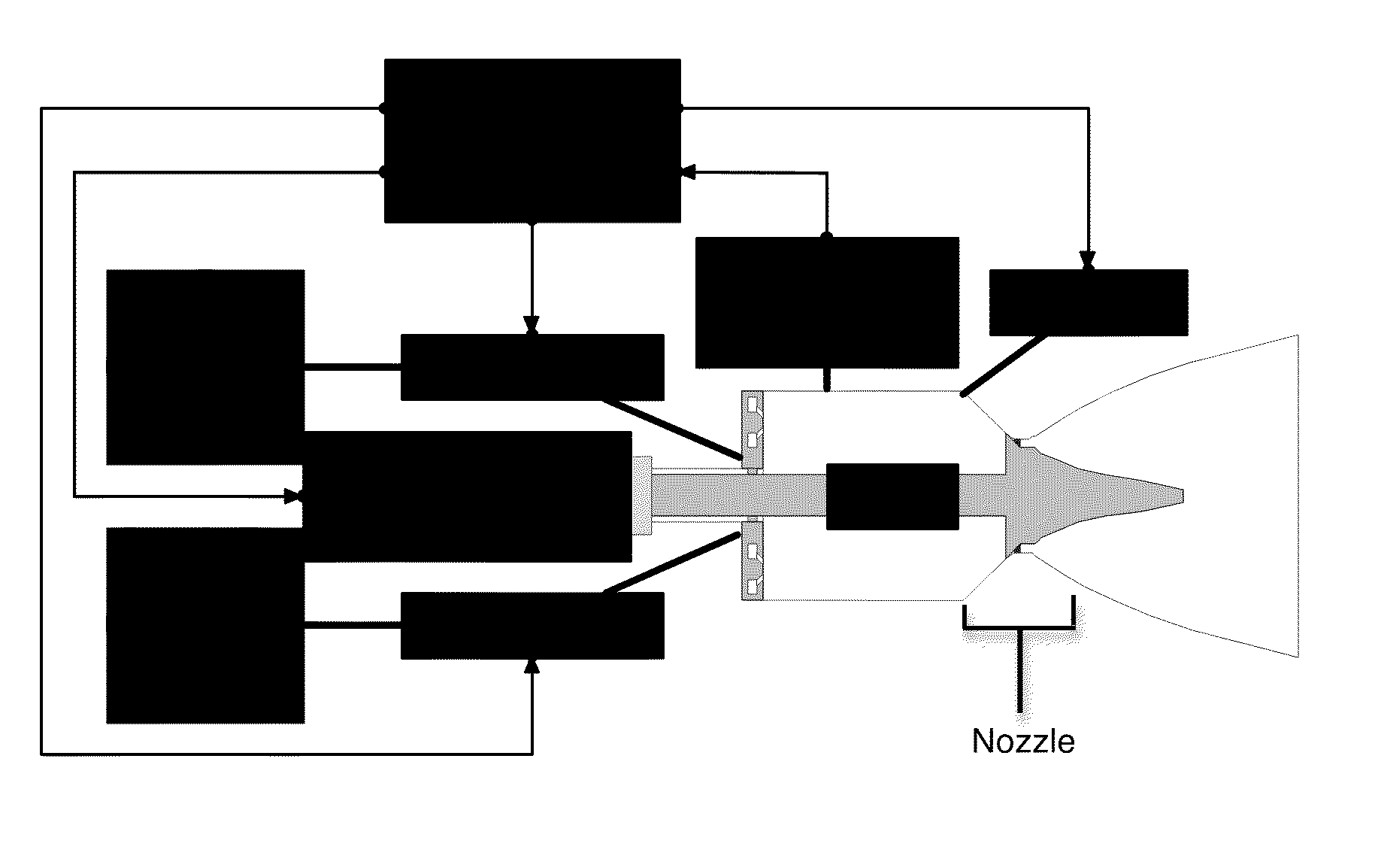
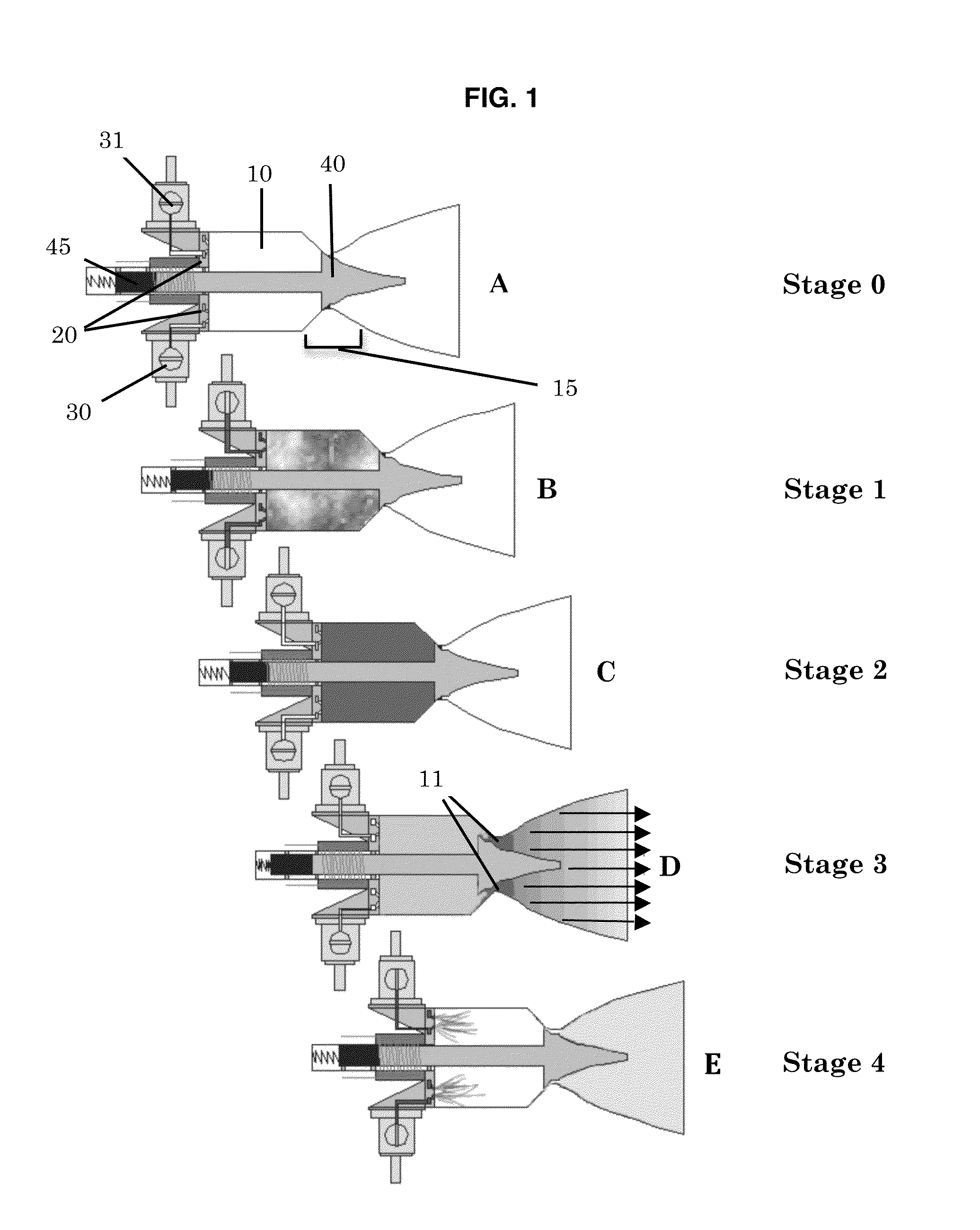
[0020]The present invention is a constant-volume rocket thruster featuring a Reciprocating Thrust Valve (RTV) mechanism with a canted-coil reciprocating seal that enables a pulse-rocket operating cycle without detonations. This configuration provides advantages over conventional constant-pressure thrusters. For example, pressure in the constant-volume combustion chamber is low during propellant injection, whereas propellant injected into a constant-pressure combustion chamber must overcome the high pressure in the combustion chamber. Consequently, constant-pressure engines require extremely high pressure tanks or turbines to force propellant into the combustion chamber. The constant volume motor requires minimal force to control propellant injection. The elimination of turbines and high pressure tanks reduces the overall weight of the vehicle. The RTV configuration provides higher-efficiency, short duration pulses than constant-pressure and pulse detonation combustion with virtually...


PUM


Abstract

The present invention is a constant volume rocket motor that uses a non-detonating constant-volume, bipropellant combustion process in pulse-mode operation. Opening and closing of the combustion chamber exhaust outlet is controlled by an actuated reciprocating thrust valve (RTV). Fuel enters the combustion chamber at low pressure with the RTV closed. The valve opens after or during combustion when combustion chamber pressure is at or near maximum. The motor has applications in reaction control systems and attitude control systems in spacecraft.

Description

STATEMENT REGARDING FEDERALLY SPONSORED RESEARCH OR DEVELOPMENT[0001]The U.S. Government may have certain rights in this invention pursuant to SBIR Contract No. F49620-03-C-009 awarded by the Air Force Office of Scientific ResearchCROSS-REFERENCE TO RELATED APPLICATIONS[0002]Not ApplicableINCORPORATED-BY-REFERENCE OF MATERIAL SUBMITTED ON A COMPACT DISC[0003]Not ApplicableBACKGROUND OF THE INVENTION[0004]1. Field of the Invention[0005]The present invention is a constant-volume, Reciprocating Thrust Valve (RTV), bipropellant rocket engine. The motor provides improved reliability and fuel efficiency compared to conventional constant pressure rocket motors for precision high-performance pulse-mode propulsion and multi-use in-space thruster applications.[0006]2. Description of Related Art[0007]Conventional liquid bipropellant thrusters are designed based on a constant-pressure combustion cycle. This type of thruster is not well suited for high-precision control of large spacecraft, whic...

Claims


Application Information

Patent Timeline
Patent Type & Authority Patents(United States)
IPC IPC(8): F02K5/02
CPCF02K9/58F02K9/94F02K9/805
Inventor DISALVO, ROBERTOOSTRANDER, MARKELLIOTT, ADAM
Owner CFD RES CORP
Why Eureka
Try Eureka