Axially staged combustion system for a gas turbine engine

a gas turbine engine and combustion system technology, applied in the direction of machines/engines, mechanical equipment, lighting and heating apparatus, etc., can solve the problems of excessive no/sub>x /sub>emissions and limited mixing of the fuel provided by the secondary fuel injection assembly

Active Publication Date: 2009-12-15
SIEMENS ENERGY INC
View PDF25 Cites 37 Cited by
  • Summary
  • Abstract
  • Description
  • Claims
  • Application Information

AI Technical Summary

Problems solved by technology

Mixing of the fuel provided by the secondary fuel injection assembly is believed to be limited due to the small number of fuel / air injection spokes and orifices provided in those spokes.
Limited mixing of fuel with air may result in rich fuel zones causing high temperature combustion zones, e.g., 2000 degrees C. and, hence, excessive NOx emissions.

Method used


Image

  • Axially staged combustion system for a gas turbine engine
  • Axially staged combustion system for a gas turbine engine
  • Axially staged combustion system for a gas turbine engine

Examples


Embodiment Construction

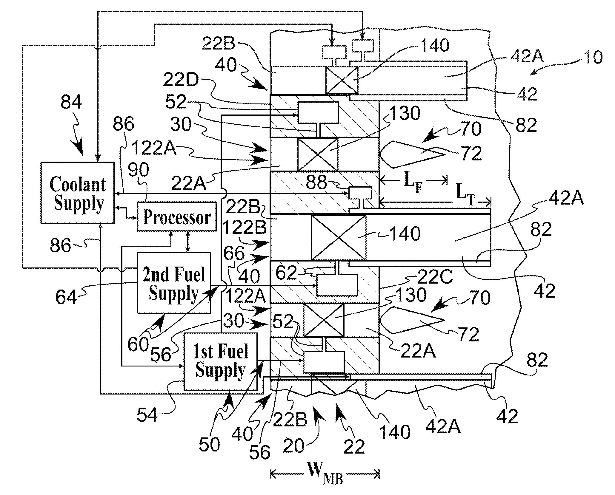
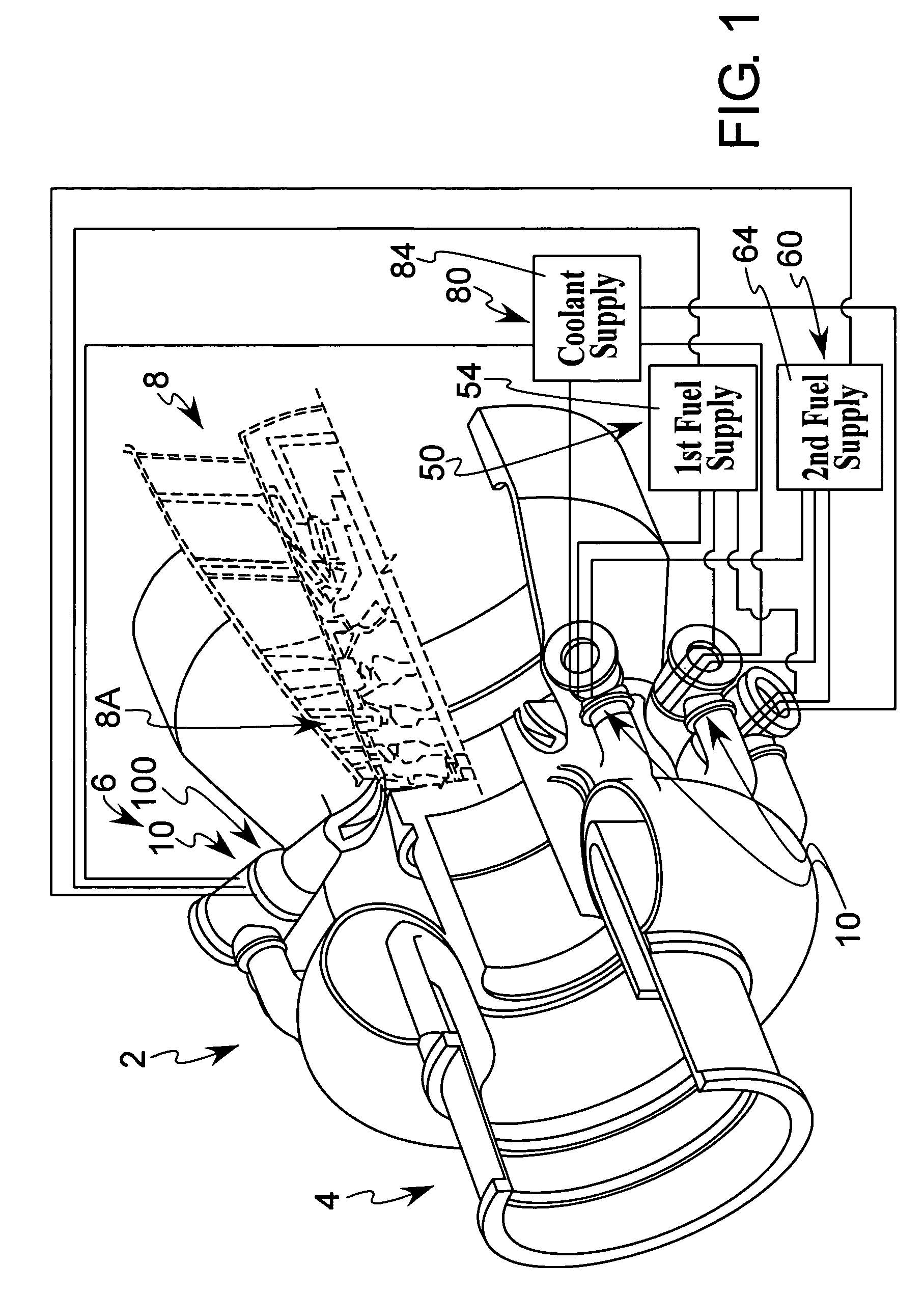
[0024]Referring now to FIG. 1, a gas turbine engine 2 is illustrated including a plurality of axially staged combustion systems 10 formed in accordance with the present invention. The engine 2 includes a compressor 4 for compressing air, a combustor 6 for producing hot combustion products or gases by burning fuel in the presence of the compressed air produced by the compressor 4, and a turbine 8 having a rotor 8A comprising a plurality of axially spaced-apart blade assemblies for receiving and being rotated by the hot combustion products produced in the combustor 6. The combustor 6 includes the plurality of axially staged combustion systems 10. The fuel may comprise, for example, natural or synthetic gas or hydrogen. The internal structure of the compressor 4 is not shown.

[0025]Since each of the combustion systems 10 forming part of the gas turbine engine combustor 6, illustrated in FIG. 1, may be constructed in the same manner, only one combustion system 10 will be described in det...


PUM


Abstract

An axially staged combustion system is provided for a gas turbine engine comprising a main body structure having a plurality of first and second injectors. First structure provides fuel to at least one of the first injectors. The fuel provided to the one first injector is adapted to mix with air and ignite to produce a flame such that the flame associated with the one first injector defines a flame front having an average length when measured from a reference surface of the main body structure. Each of the second injectors comprising a section extending from the reference surface of the main body structure through the flame front and having a length greater than the average length of the flame front. Second structure provides fuel to at least one of the second injectors. The fuel passes through the one second injector and exits the one second injector at a location axially spaced from the flame front.

Description

[0001]This invention was made with U.S. Government support under DE-FC26-05NT42644 awarded by the U.S. Department of Energy. The U.S. Government has certain rights to this invention.[0002]This application is related to U.S. patent application Ser. No. 11 / 498,479 entitled “AT LEAST ONE COMBUSTION APPARATUS AND DUCT STRUCTURE FOR A GAS TURBINE ENGINE,” which is filed concurrently herewith and hereby incorporated by reference herein.FIELD OF THE INVENTION[0003]The present invention is directed to an axially staged combustion system for a gas turbine engine.BACKGROUND OF THE INVENTION[0004]Gas combustion turbine engines are used for generating power in a variety of applications including land-based electrical power generating plants. Gas turbine engines are known to produce an exhaust stream containing a number of combustion products. Many of these byproducts of the combustion process are considered atmospheric pollutants. Of particular concern is the production of the various forms of ...

Claims


Application Information

Patent Timeline
Patent Type & Authority Patents(United States)
IPC IPC(8): F23R3/42
CPCF23C6/047F23R3/346F23R3/286F23R3/283F23M2900/05004
Inventor BLAND, ROBERT J.
Owner SIEMENS ENERGY INC
Why Eureka
Try Eureka