Coanda gas burner apparatus and methods

a gas burner and coanda technology, applied in the direction of lighting and heating apparatus, combustion types, transportation and packaging, etc., can solve the problems of difficult ignition, unstable ignited flame, and the coanda surface has not been incorporated into low-nosub>x/sub>process burner apparatus, etc., to enhance the mixing of flue gas, enhance stability, and prolong the turndown capability

Active Publication Date: 2011-02-01
JOHN ZINK CO LLC
View PDF93 Cites 33 Cited by
  • Summary
  • Abstract
  • Description
  • Claims
  • Application Information

AI Technical Summary

Benefits of technology

[0009]In accordance with the present invention, gas burner apparatus and methods are provided which meet the needs described above and overcome the deficiencies of the prior art. It has been discovered that a Coanda surface can be coupled with a free fluid stream to mix fuel gas with air and a diluent (furnace flue gas in this case) while maintaining extended turndown capabilities and enhanced stability. The Coanda surface greatly enhances mixing of the flue gas with the other fluids in the stream. Further, by the use of various Coanda surfaces, the amount of flue gas that can be incorporated into a mixing zone and flame can be greatly increased. Thus, the ability to reduce nitrous oxide and carbon monoxide emissions from the burner can be greatly increased while improving flame quality and heat flux distribution in the furnace. The Coanda surfaces and the way the surfaces are positioned on the inside and outside of the burner tile allow the flue gas to be imparted to various mixing and combustion zones associated with the burner without diluting the fuel gas on the inner boundary layer to a point that it becomes non-combustible or results in an instable flame. The Coanda surfaces also allow the shape of the flame to be accurately controlled without the need for other structures such as flame-holders, cones, wings, impingement plates and so forth. These and other advantages of the invention are described in detail below.

Problems solved by technology

However, if the fuel gas is overly diluted, it may be difficult to ignite or the ignited flame may become unstable.
However, Coanda surfaces have not been incorporated into low NOX process burner apparatus.
As a result, Coanda technology has not been actively applied to process burners.
Also, many refinery operators have not changed the refinery furnaces due to the expense involved therewith.

Method used


Image

  • Coanda gas burner apparatus and methods
  • Coanda gas burner apparatus and methods
  • Coanda gas burner apparatus and methods

Examples


example

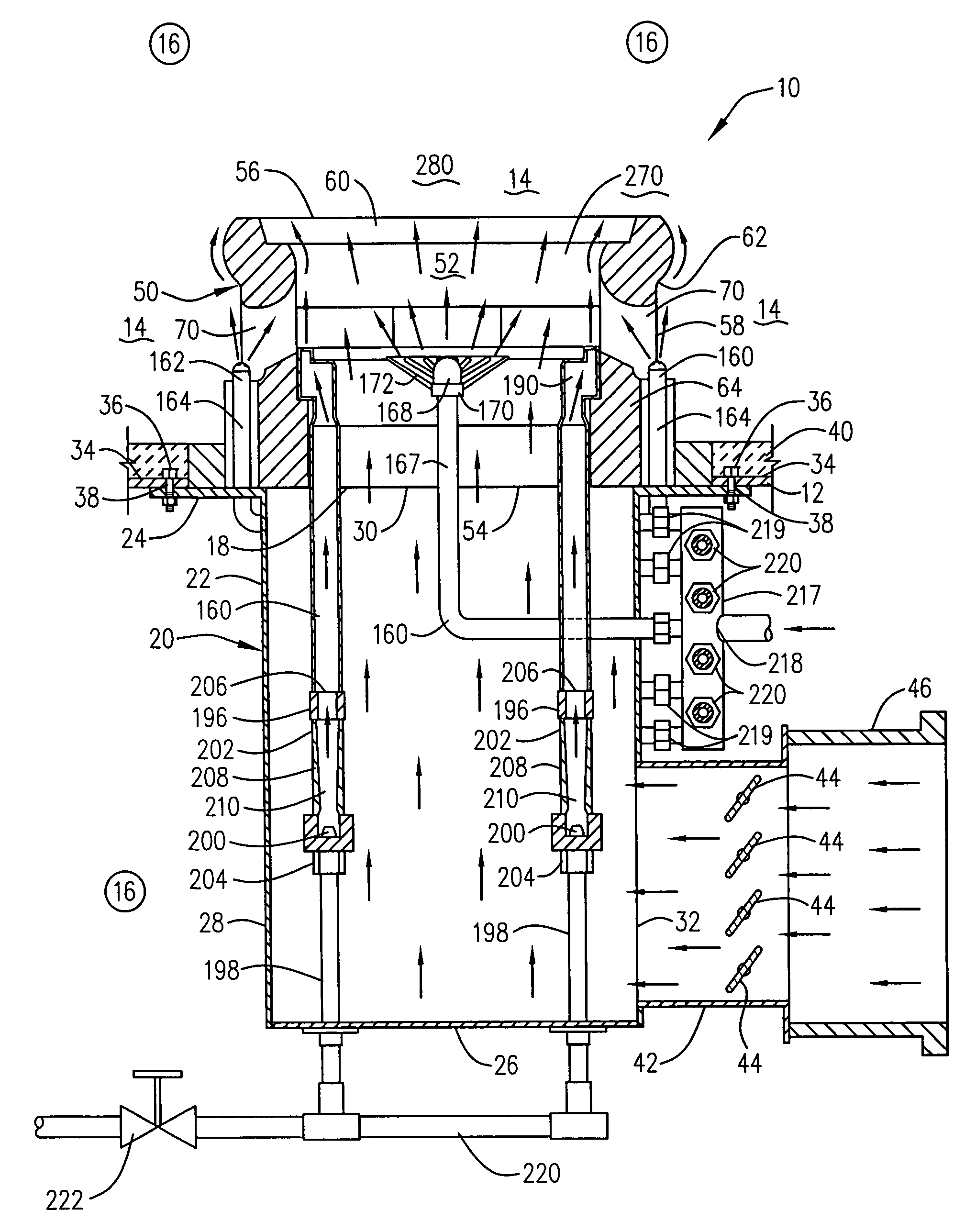
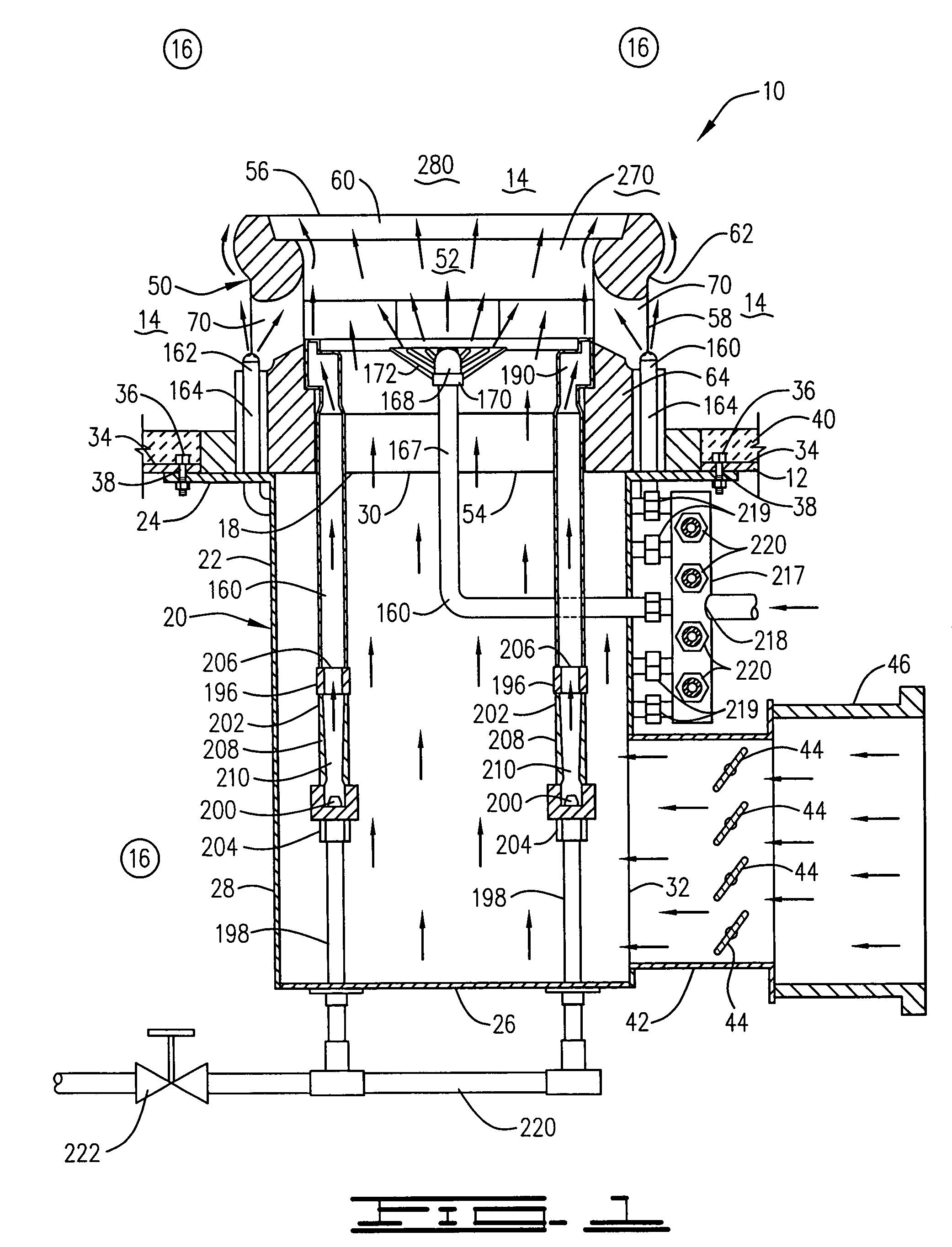
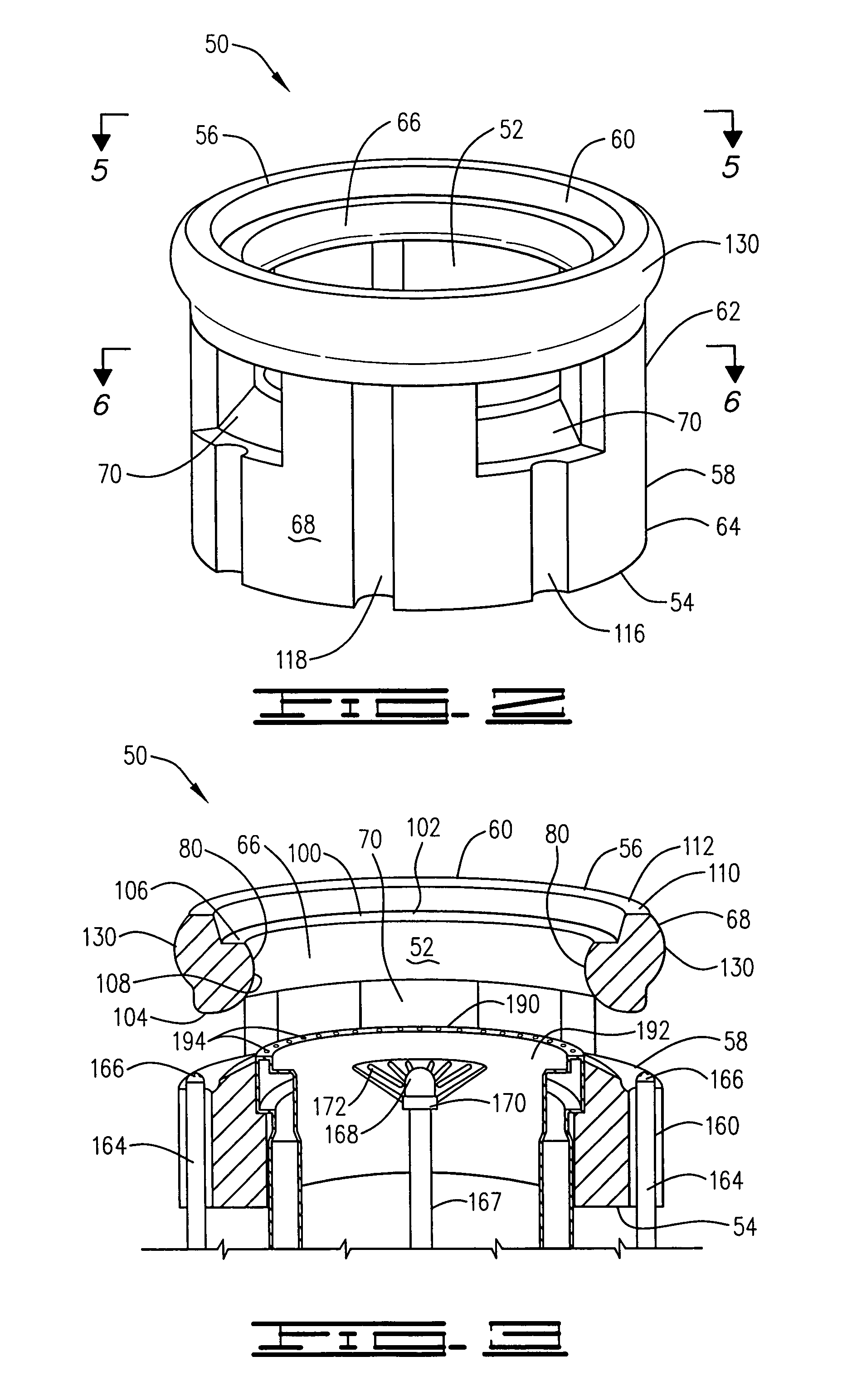
[0124]The inventive gas burner apparatus 10 was tested for performance. The internal Coanda surfaces 80 and a continuous Coanda surface 130 were included on the wall 58 of the burner tile 50. The primary fuel gas injection means in the particular burner configuration tested included the outer gas risers 164 and fuel gas discharge nozzles 166. The fuel gas discharge nozzles included both ports for injecting primary fuel gas through the gas circulation ports 80 and ports for injecting secondary fuel gas on or adjacent to the external Coanda surface 130. The pre-mix unit 190 was also utilized to reduce nitrous oxide emissions. The pre-mix membrane 192 included 36 pre-mix gas ports 194 that had a 0.261 inch diameter. These ports were spaced around the top surface of the pre-mix membrane 192. Each 0.261 inch port had a 0.125 inch port located between it that was also counter-bored with a 0.125 inch diameter port superimposed over it. The purpose of the smaller ports was to serve as an ig...


PUM


Abstract

A gas burner apparatus for discharging a mixture of fuel gas, air and flue gas into a furnace space of a furnace wherein the mixture is burned and flue gas having a low content of nitrous oxides and carbon monoxide is formed is provided. The burner tile includes at least one gas circulation port extending though the wall of the tile. The interior surface of the wall of the tile includes a Coanda surface. Fuel gas and / or flue gas conducted through the gas circulation port follows the path of the Coanda surface which allows more flue gas to be introduced into the stream. The exterior surface of the wall of the tile also includes a Coanda surface for facilitating the creation of a staged combustion zone. Also provided are improved burner tiles, improved gas tips and methods of burning a mixture of air, fuel gas and flue gas in a furnace space.

Description

BACKGROUND OF THE INVENTION[0001]The present invention relates to gas burner apparatus and methods of burning fuel gas in the presence of air and furnace flue gas to create a stable flame while suppressing the formation of nitrous oxides (“NOx”) and carbon monoxide (“CO”).[0002]Various types of gas burners have been developed and successfully utilized with a combination of both diffusion and pre-mix capabilities. A pre-mix approach mixes both the air and fuel gas to a homogenous mixture prior to combustion within the confines of the furnace. A diffusion approach injects the fuel gas into an air stream wherein mixing takes place without a venturi. The flame is stabilized close to the point of exit, creating both thermal and prompt nitrous oxides. Both approaches are routinely utilized to ignite and combust a given fuel gas to generate heat within a process burner.[0003]In both pre-mix and diffusion-type burners, an optimum approach can be defined to reduce both thermal and prompt nit...

Claims


Application Information

Patent Timeline
Patent Type & Authority Patents(United States)
IPC IPC(8): F23M3/00
CPCF23D14/08F23M5/025F23D14/84Y02E20/12Y10T137/2224Y10T137/2076F23D14/20F23D14/00
Inventor POE, ROGER L.WILKINS, JAMESCLAXTON, MICHAEL G.
Owner JOHN ZINK CO LLC
Why Eureka
Try Eureka