
Staged combustion systems and methods

a staged combustion and combustion technology, applied in the direction of efficient propulsion technologies, machines/engines, lighting and heating apparatus, etc., can solve the problems of incomplete combustion, reduced design options for axially staged combustors, and more heat damage to second stage injectors, so as to reduce undeired emissions and design flexibility

Inactive Publication Date: 2010-04-22
GENERAL ELECTRIC CO
View PDF20 Cites 33 Cited by
  • Summary
  • Abstract
  • Description
  • Claims
  • Application Information

AI Technical Summary

Benefits of technology

[0009]It would be desirable to have more flexibility in design of axially staged combustion systems and to reduce undesired emissions in such combustion systems.

Problems solved by technology

An initial flame zone (or first stage) of a staged combustor typically has a low flame temperature and a long residence time to balance NOx and carbon monoxide requirements.
Thus the second stage injector is more prone to heat damage.
Combustion characteristics of the fuel often limit design options in axially staged combustors.
For example, slow reaction rates can result in incomplete combustion and the emission of carbon monoxide and unburned hydrocarbons.
On the other hand, reaction rates that are too high can lead to flameholding where the second stage reaction zone is located so close to the seconds stage injector that it can sustain damage.
Finally, poor mixing between the second stage fuel and primary stage products can exacerbate both of the problems mentioned above in addition to causing hot flame zones that produce higher NOx, poorly stabilized flames, and other problems.

Method used


Image

  • Staged combustion systems and methods
  • Staged combustion systems and methods
  • Staged combustion systems and methods

Examples


Embodiment Construction

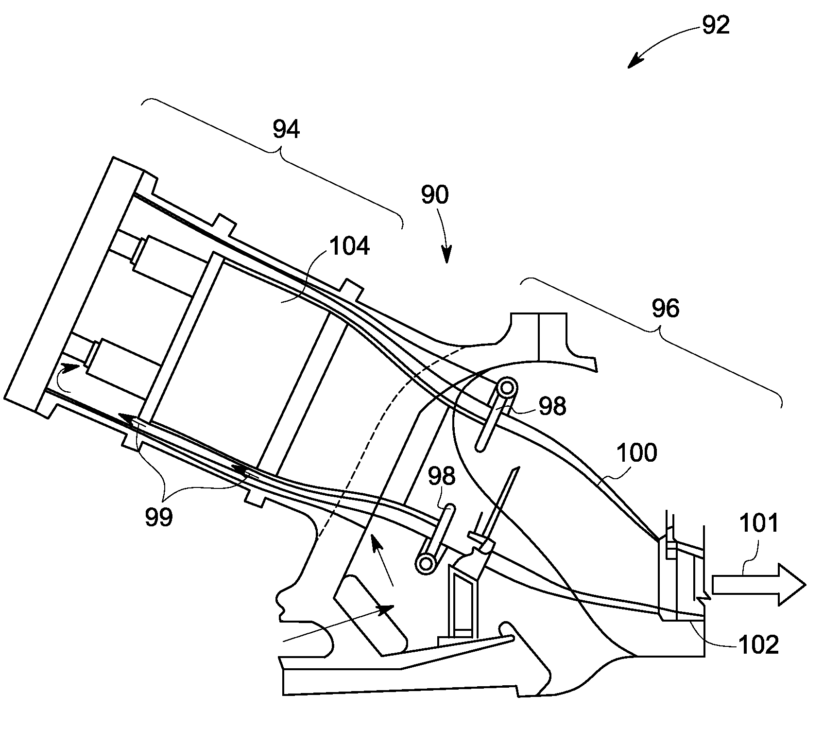
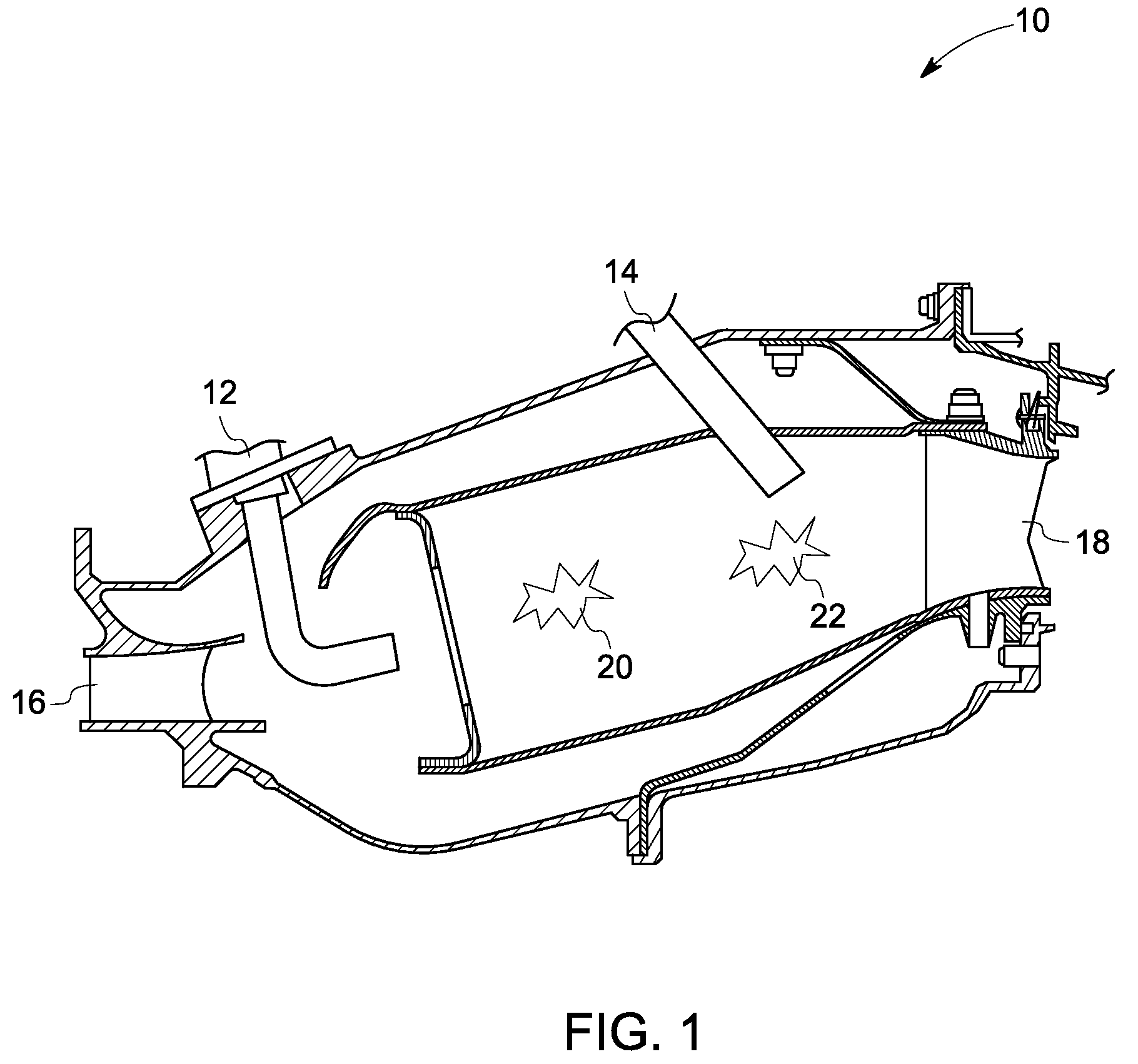
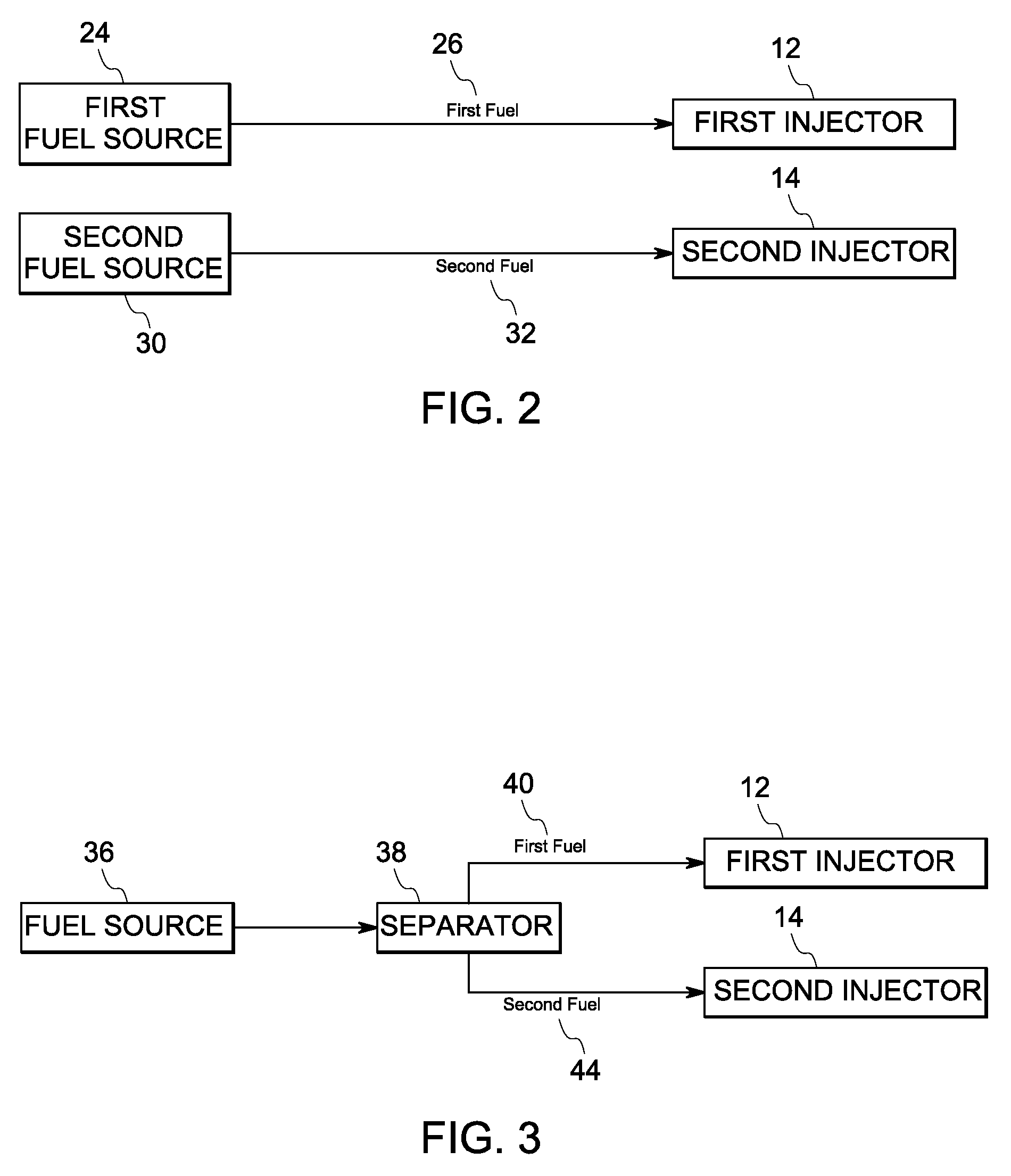
[0019]In one embodiment, as shown in FIG. 1, a staged combustion system 10 comprises: a first fuel source for supplying a first fuel having a first chemical composition, a second fuel source for supplying a second fuel having a second chemical composition, such that a relative reactive concentration of one or more of hydrogen, carbon monoxide, a hydrocarbon, or a combination of two or more hydrocarbons n, in the first chemical composition is different from that of the second chemical composition. As used herein a different “relative reactive concentration” means a different concentration among the reactive components (hydrogen, carbon monoxide, a hydrocarbon, or a combination of two or more hydrocarbons), regardless of whether one or both of the fuels may have one or more non-reactive components such as nitrogen, carbon dioxide, and steam. In other words, if non-reactive components were to be removed from the first and second fuels, the resulting chemical compositions would still be...


PUM


Abstract

Systems and methods for staged combustion are provided. One staged combustion system includes a first fuel source for supplying a first fuel having a first chemical composition, a first injector for injecting the first fuel, a second fuel source for supplying a second fuel having a second chemical composition such that a relative reactive concentration of one or more of hydrogen, carbon monoxide, a hydrocarbon, or a combination of two or more hydrocarbons, in the first chemical composition is different from that of the second chemical composition, and a second injector situated for injecting the second fuel downstream of the first injector.

Description

STATEMENT OF FEDERALLY FUNDED RESEARCH[0001]This invention was made with Government support under contract number DE-FC26-05NT42643 awarded by the Department of Energy. The Government has certain rights in the invention.BACKGROUND[0002]Embodiments of the invention relate to staged combustion systems and methods.[0003]Various types of gas turbine systems exist. For example, aeroderivative gas turbines are employed for applications such as power generation, marine propulsion, gas compression, cogeneration, and offshore platform power. A gas turbine system generally includes a compressor for compressing an sir flow, a combustor that combines compressed air with fuel and ignites the mixture to generate a working gas, and a turbine section for expanding the working gas and generating power. The combustor is generally arranged coaxially with the compressor and the turbine section.[0004]It is advantageous for the combustors of the gas turbine systems to minimize emissions such as nitrogen ...

Claims


Application Information

Patent Timeline
Patent Type & Authority Applications(United States)
IPC IPC(8): F02C3/20F02C7/22
CPCF02C7/22F02C9/40F05D2270/082Y02T50/677F23R3/36F23R2900/00002F23R3/346Y02T50/60
Inventor BLOUCH, JOHN DEWEYYILMAZ, ERTANVARATHARAJAN, BALACHANDAR
Owner GENERAL ELECTRIC CO
Learn More