Kit for seat rows in aircraft

a seat row and seat technology, applied in the field of seat rows, can solve the problems of specific parts or connection adapters, and achieve the effect of stable connection, easy production and assembly

Active Publication Date: 2013-03-12
ZIM AIRCRAFT SEATING GMBH
View PDF21 Cites 35 Cited by
  • Summary
  • Abstract
  • Description
  • Claims
  • Application Information

AI Technical Summary

Benefits of technology

[0009]According to the present invention, in practice it has proved advantageous if the seat dividers together with the support legs are fastened to the spars according to the disk hub principle, this type of disk hub connection being able to be formed by corresponding disk hub halves.
[0017]The preforming of the floor required by the approved regulations, in this case known as pitch and roll, provides a very high level of pretensioning in the primary structure of the seat, in particular in the supporting tubes, seat dividers and seat legs. With the predetermined pitch and roll, on the one hand, one seat rail is displaced downwards by a predetermined value and the other seat rail is additionally rotated by a specific angle. This pretensioning is superimposed by the actual load of a 16 G crash load case. A reduction of the pretensioning leads to more reliable proof of compliance and / or permits a more lightweight design of the primary structure.
[0019]According to the present invention, the supporting tubes are connected via half-shells to the seat legs. In this connection, frictional values defined by the half-shell design may be set, in order to permit the slipping of the supporting tube at least to the smallest extent, in the case of pitch and roll. Moreover, each of the half-shells present is individually screwed and thus individually deformable and flexible per se, so that due to a flexibility of the individual half-shells, as a result of the load, an optimal slipping of the supporting tubes and thus an unloading of the seat structure is ensured.
[0020]Advantageously, in each case the through-holes should be in the half-shells and the associated thread in the seat foot / seat divider. By the construction of the multiple half-shells it is possible that the half-shells may move relative to one another. Thus, on the one hand, a very stable connection is achieved, which however at the same time permits a flexibility and relative movement which is defined to a certain extent. By the pretensioning by means of a predetermined screw tightening torque, a non-positive and frictional connection is made which, however, in the case of pitch and roll also permits a certain flexibility, even before it could lead to failure of the structural components, and to a certain extent even has a specific restoring capacity in order to deform but not break the components.
[0021]The modular design according to the present invention permits this. Different offset solutions do not have to be provided, but all the usual seating configurations may be set and also easily produced and assembled.

Problems solved by technology

In this type of connection, there is the drawback that when the seat leg comes into contact with the seat divider, specific parts or connection adapters are necessary.

Method used


Image

  • Kit for seat rows in aircraft
  • Kit for seat rows in aircraft
  • Kit for seat rows in aircraft

Examples


Embodiment Construction

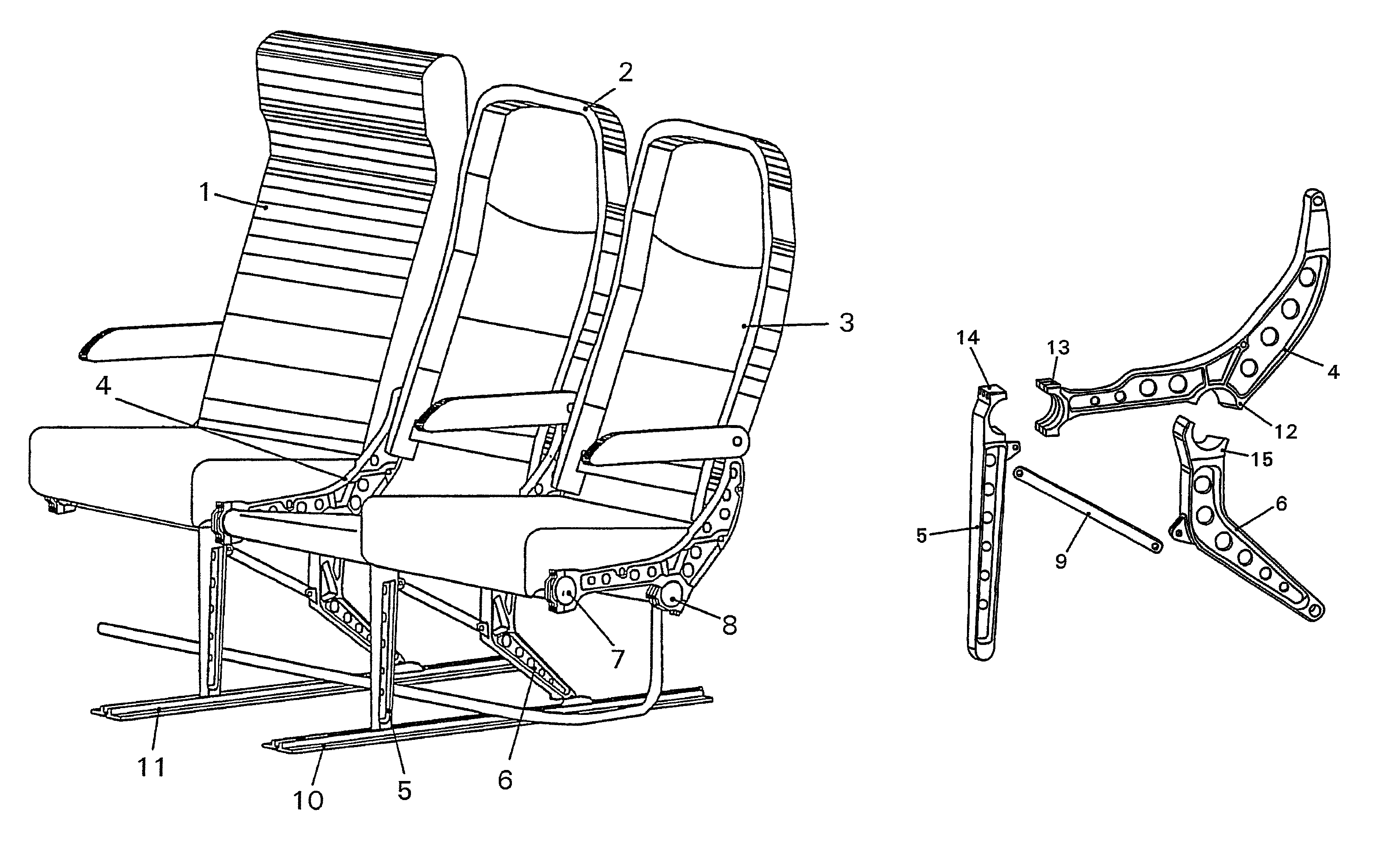
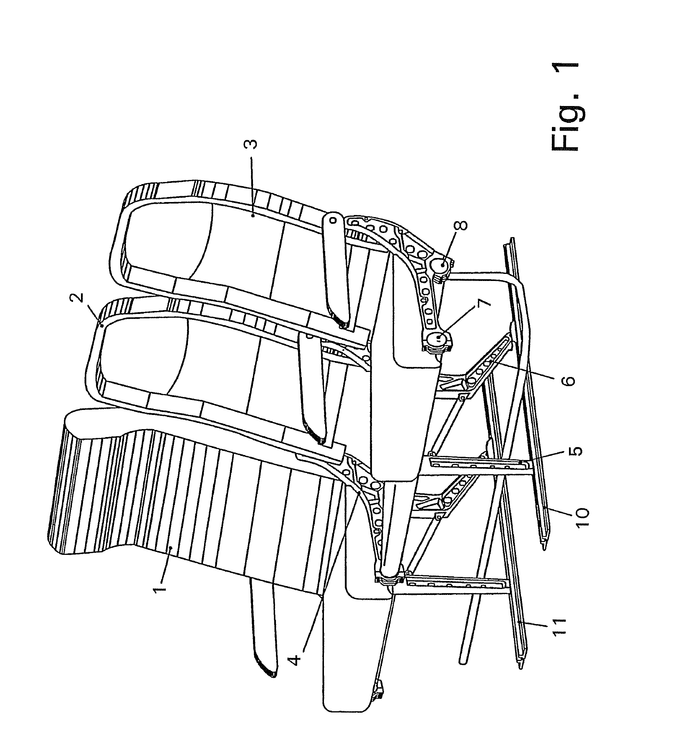
[0027]The seat row comprising three seats, shown by way of example in FIG. 1, in particular for installing in aircraft, shows a seat 1 complete with upholstery, to the right thereof a seat 2 where the upholstery is still absent and a seat 3 on which only one seat cushion rests.

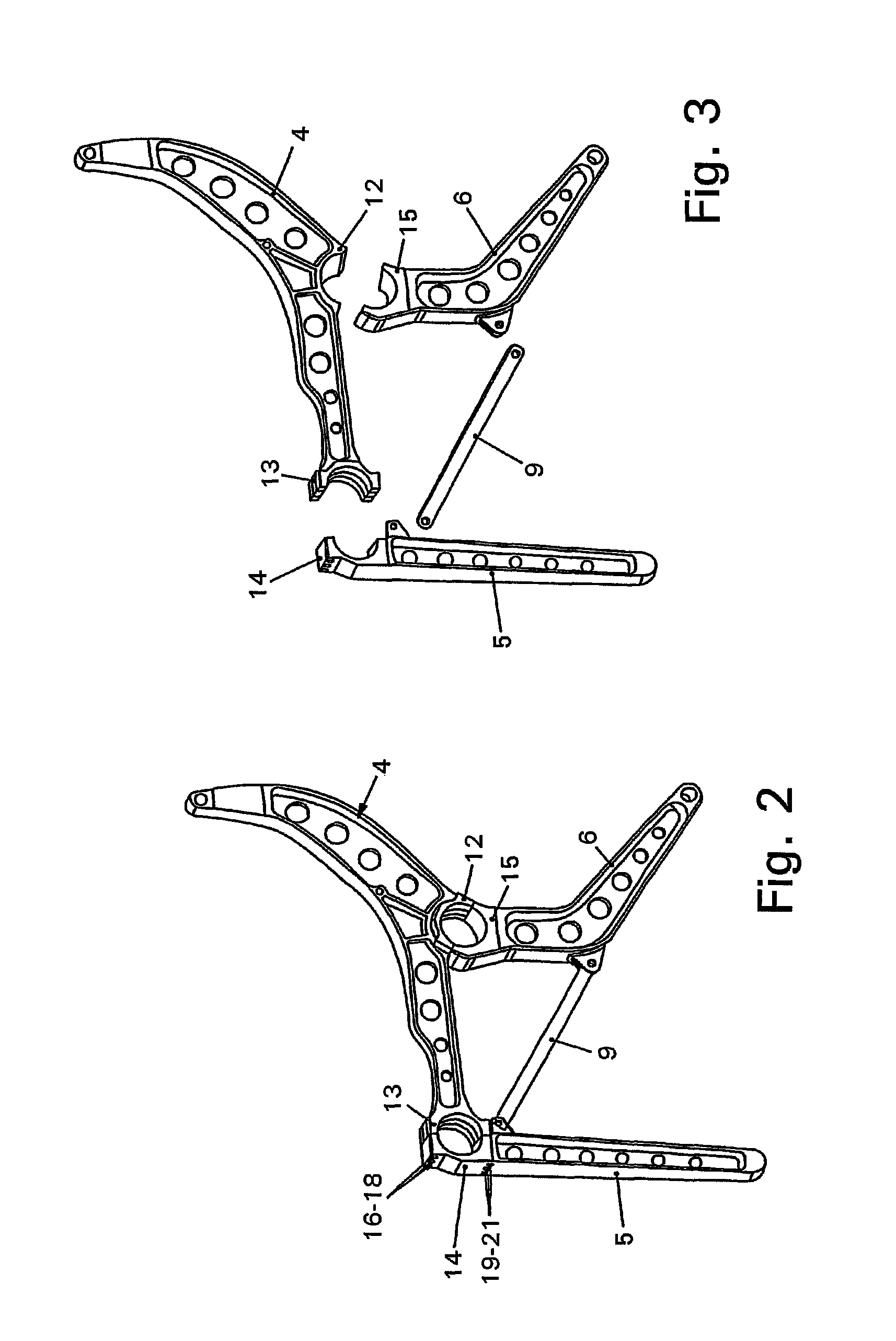
[0028]Between the seats 1-3 are located identical seat dividers 4 which are connected together by identical support legs 5 and 6 according to the principle of a disk hub connection with tubular spars 7 and 8 running transversely to the seat direction and extending parallel to one another. Moreover, the support legs 5 and 6 are supported against one another by a strut 9 (see FIG. 2).

[0029]The support legs 5 and 6 on both sides of the central seat 2, which are guided in floor rails 10 and 11, carry substantially the same seat row consisting of the seats 1-3.

[0030]In FIG. 2 the load-bearing component consisting of the seat dividers 4, the support legs 5 and 6 as well as the strut 9 are shown screwed-together, whi...


PUM


Abstract

In seat rows, in particular in aircraft, the individual seats thereof being able to be adjusted in their usable seat width, and comprising seat dividers with support legs, which are held by spars running transversely to the seat direction, at least one seat divider may be adjusted in the direction of the spars.

Description

CROSS REFERENCE TO RELATED APPLICATIONS[0001]This application is a continuation of International Application No. PCT / EP2009 / 003262 filed May 7, 2009, which designated the United States, and claims the benefit under 35 USC §119(a)-(d) of German Application No. 10 2008 022 671.8 filed May 7, 2008 and German Application No. 10 2008 039 262.6 filed Aug. 22, 2008, the entireties of which are incorporated herein by reference.FIELD OF THE INVENTION[0002]The invention relates to seat rows, in particular in aircraft, the individual seats thereof being able to be adjusted in their usable seat width, and comprising seat dividers and support legs, which are held by spars running transversely to the seat direction.BACKGROUND OF THE INVENTION[0003]It is known from DE 39 18 500 C2 to fasten the seat divider or even the seat foot to a supporting tube. The seat foot is fastened by means of a tensioning strap to the supporting tube and the seat divider is fastened in the front region by means of a pr...

Claims


Application Information

Patent Timeline
Patent Type & Authority Patents(United States)
IPC IPC(8): A47C15/00A47B97/00
CPCB64D11/0693
Inventor ZIMMERMANN, PETERSOETEBIER, ULFISELE, FRANKGRUNBERG, JURGEN
Owner ZIM AIRCRAFT SEATING GMBH
Why Eureka
Try Eureka