System and method for automatically designing communications circuits

a communication circuit and automatic design technology, applied in the field of communication, can solve the problems of limiting the ability of network providers to transfer personnel, affecting the efficiency of network providers, and affecting the implementation efficiency of manual circuit design techniques, etc., and achieves the effect of substantially reducing the disadvantages and problems of previous techniques for designing communications circuits

Inactive Publication Date: 2005-05-10
AGILE SOFTWARE CORPORATION
View PDF15 Cites 36 Cited by
  • Summary
  • Abstract
  • Description
  • Claims
  • Application Information

AI Technical Summary

Benefits of technology

[0006]According to the present invention, disadvantages and problems associated with previous techniques for designing communications circuits are substantially reduced or eliminated.
[0008]The present invention provides a number of important advantages over prior circuit design techniques. Unlike previous techniques, the introduction of route plans based on route point groups allows the optimal routing for a circuit to be determined automatically based on strategic plans, available capacity, diversity criteria, and other suitable factors, resulting in faster, more consistent, and more efficient designs. The present invention automates many processes performed manually in prior techniques, relieving design personnel of the burden of intimate familiarity with the network and helping network providers respond more quickly, consistently, and reliably to customer requests for circuits. For example, selection and assignment of qualified facilities may be made automatically, without regard to the physical layer technology associated with the facilities. Required equipment for a specific type of circuit may be automatically selected and assigned according to suitable equipment assignment templates.
[0009]Other aspects of the circuit design process, automated according to the present invention, benefit the network provider and its customers in a variety of ways. As an example, personnel may be transferred into and out of design positions more readily, giving the network provider increased flexibility. The present invention also allows controls to be readily placed on the design process, helping ensure that circuit designs adhere to network plans when possible and, if not possible, that design violations are logged and flagged for subsequent remediation. In contrast to previous techniques, the present invention allows network planning and other business intelligence to be readily incorporated into the circuit design process. As an example, factors such as demand, capacity, and load balancing may be considered automatically in connection with route selection and assignment to facilitate network optimization.

Problems solved by technology

The requirement that designers be intimately familiar with networks may often limit the ability of network providers to transfer personnel into or out of design positions, hampering flexibility within these organizations.
Even with the availability of prior software tools, these manual circuit design techniques have been relatively difficult, slow, inconsistent, and otherwise inefficient in their implementation.
When facilities, equipment, or other circuit elements associated with an existing circuit are added, deleted, modified, or otherwise acted upon, the design must be re-validated using the same inefficient processes.
If made erroneously, such decisions may undermine the reliability of the network and result in substantial losses to the network provider and its customers.
Prior techniques do not readily allow network planning intelligence to be incorporated into the route selection process.
As communications needs continue to expand, and network providers seek ways to respond more rapidly, consistently, and efficiently to growing demand for circuits, these and other problems are exacerbated.
These and other deficiencies have made prior techniques inadequate for the needs of many network providers.

Method used


Image

  • System and method for automatically designing communications circuits
  • System and method for automatically designing communications circuits
  • System and method for automatically designing communications circuits

Examples


Embodiment Construction

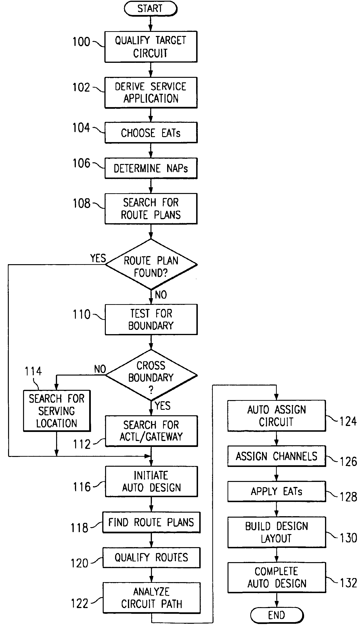
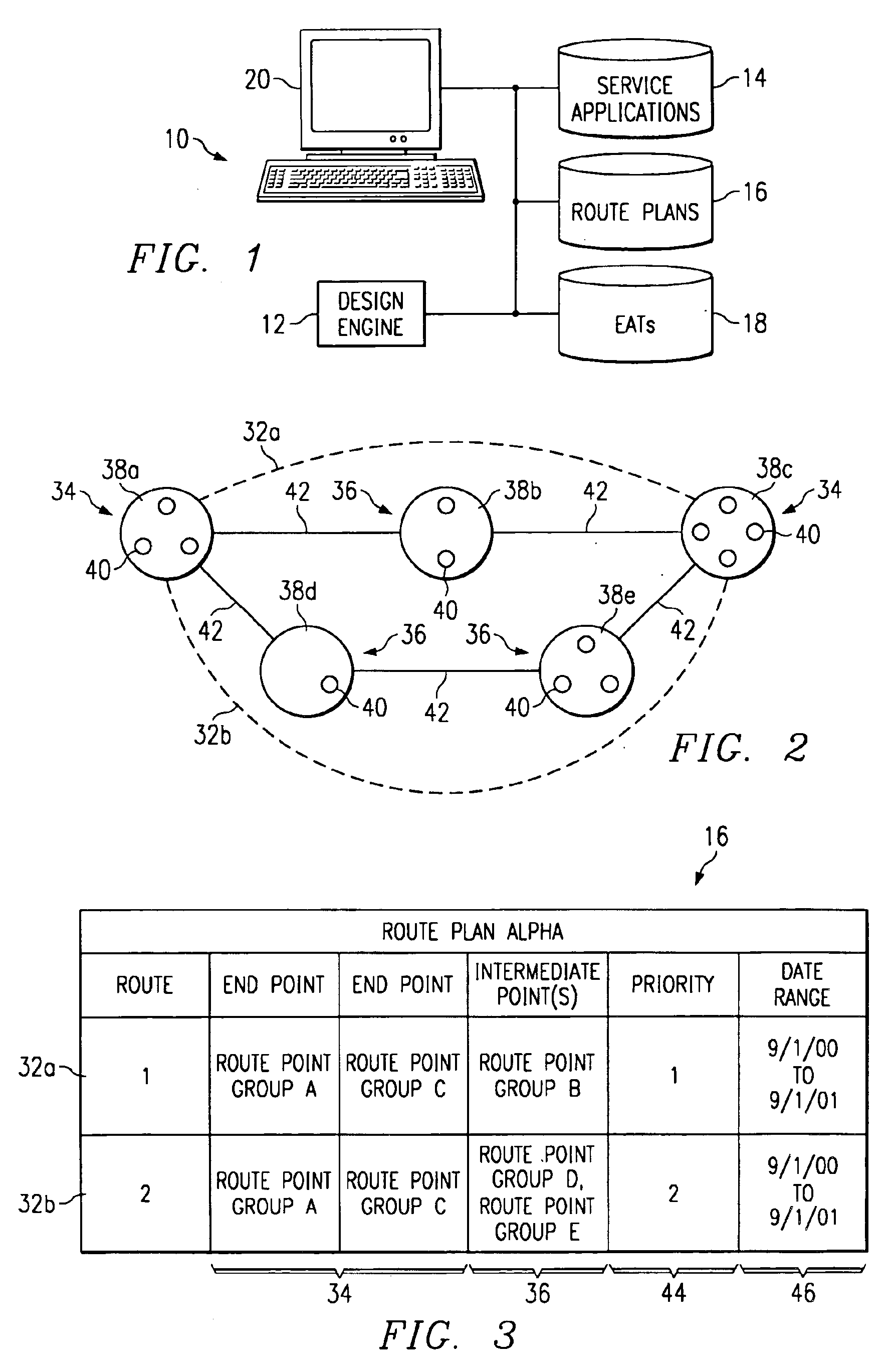
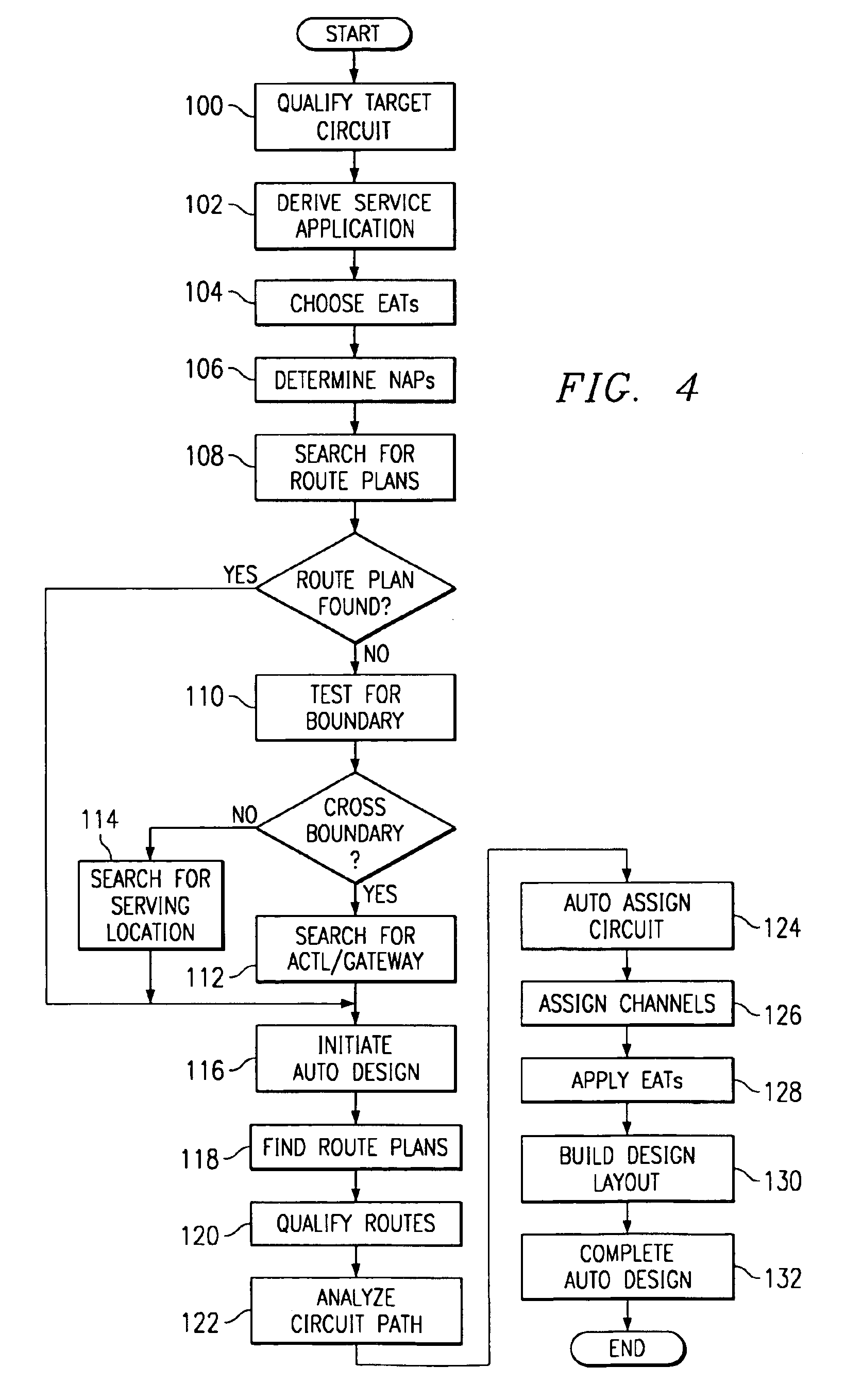
[0021]Communications circuits connect network locations to enable communications between these locations, possibly through one or more intermediate locations. As an example, a circuit might be a circuit that connects two end users; a trunk circuit that connects two switching systems, a Signaling System No. 7 (SS7) link that connects a Signaling Transfer Point (STP) to a Service Switching Point (SSP), to another STP, or to a Service Control Point (SCP); a “911” or other emergency services circuit; a circuit including nodes on a Synchronous Optical Network (SONET) ring; a permanent virtual circuit (PVC), virtual connection, or link relying on Frame Relay (FR), Asynchronous Transfer Mode (ATM), Internet Protocol (IP), or any other packet-based protocol; a “bandwidth” circuit incorporating a physical circuit that virtual circuits “ride” using portions of its available bandwidth; or any other suitable circuit. The present invention encompasses the automatic design of any appropriate circ...


PUM


Abstract

A software interface used in designing communications circuits receives input from a user (20). In response, the software interface initiates accessing of a route plan (16) comprising a first route point group (38) associated with a first circuit end point (34), a second route point group (38) associated with a second circuit end point (34), and one or more routes (32) connecting the first and second route point groups (38). Each route (32) is available for use in designing the circuit. The software interface also initiates selection of a route (32) according to the route plan (16) and initiates the automatic assignment of the selected route (32) to the circuit in designing the circuit. The software interface provides information to the user (20) reflecting assignment of the route (32) to the circuit. The route plan (16) may be selected from among multiple route plans (16) according to a service application (14) automatically derived from an associated circuit order. The software interface may initiate assignment of equipment to the circuit at one or more points along the selected route (32) according to an equipment assignment template (18) specifying characteristics of the equipment. The template (18) may be selected from among multiple templates (18) according to a service application (14).

Description

CROSS-REFERENCE TO RELATED APPLICATIONS[0001]This application claims the benefit under 35 U.S.C. § 119(e) of U.S. Provisional Application Ser. No. 60 / 232,324, filed Sep. 13, 2000.[0002]This application is related to U.S. application Ser. No. 09 / 736,902 entitled “System and Method for Automatically Designing Communications Circuits” filed Dec. 13, 2000 by David C. Campbell, Brenda D. Dunn, Mark W. McGuire, Joseph A. Peterson, John P. Reilly, Mary Kim Westervelt, now U.S. Pat. No. 6,643,837, and U.S. application Ser. No. 09 / 736,903 entitled “System and Method for Designing Diverse Communications Circuits” filed Dec. 13, 2000 by David C. Campbell and Mary Kim Westervelt, now U.S. Pat. No. 6,802,044.TECHNICAL FIELD OF THE INVENTION[0003]The invention relates in general to the field of communications and in particular to a system and method for automatically designing communications circuits.BACKGROUND OF THE INVENTION[0004]Network plans for voice, data, and other communications networks...

Claims


Application Information

Patent Timeline
Patent Type & Authority Patents(United States)
IPC IPC(8): G06F17/50H04L12/24
CPCH04L12/24H04L49/65H04L41/00H04L41/22
Inventor CAMPBELL, DAVID C.DUNN, BRENDA D.MCGUIRE, MARK W.PETERSON, JOSEPH A.REILLY, JOHN P.WESTERVELT, MARY KIM
Owner AGILE SOFTWARE CORPORATION
Why Eureka
Try Eureka