Divided-chamber gas engine

a gas engine and divided chamber technology, applied in combustion engines, machines/engines, cylinders, etc., can solve the problems of cracks, thermal fatigue in the inner wall of the auxiliary chamber, and unnecessary installation of denitration devices, so as to suppress degradation of combustion performance and prevent deformation of the nozzle cross section

Inactive Publication Date: 2013-01-03
KAWASAKI HEAVY IND LTD
View PDF12 Cites 33 Cited by
  • Summary
  • Abstract
  • Description
  • Claims
  • Application Information

AI Technical Summary

Benefits of technology

[0018]In the divided-chamber gas engine according to the present invention, the edge of the inlet of each nozzle at the auxiliary combustion chamber side is formed into a curved surface. Therefore, at the inlet of the nozzle, there is no edge that tends to be chipped. This makes it possible to suppress a phenomenon where cracked portions partially come off, to prevent deformation of the nozzle's cross section, and to suppress degradation in the combustion performance in the main combustion chamber.

Problems solved by technology

Therefore, for performing lean burn, the installation of a denitration device is unnecessary in some cases.
Due to such heating and cooling cycles, the inner wall of the auxiliary chamber is subjected to thermal fatigue.
As a result, cracks occur.
In particular, cracks mainly occur near the nozzles' opening edges at the auxiliary chamber side.
If the severity of the cracks near the nozzles' opening edges at the auxiliary chamber side increases, then cracks also occur in the inner wall of the nozzles.
If a high-temperature jet flame passes through such a cracked inner wall of a nozzle, then cracked portions partially come off, resulting in chipping of the edge of the nozzle's inlet (i.e., chipping of the opening edge), or the inner wall of the nozzle or the inner wall of the auxiliary chamber at the rim of the nozzle peels off, causing its surface to become rough.
Chipping and cracks at the edge of the inlet of the nozzle cause a change in the intensity of a jet flame, which may lead to a decrease in the engine's combustion performance.
In this case, there is a possibility that the length of the jet flame becomes insufficient.
Moreover, the degree of such chipping and cracks is not necessarily the same among a plurality of nozzles.
If an ignition environment in the main chamber becomes less uniform than that originally designed, it may result in a decrease in the engine's combustion efficiency.

Method used


Image

  • Divided-chamber gas engine
  • Divided-chamber gas engine
  • Divided-chamber gas engine

Examples


Embodiment Construction

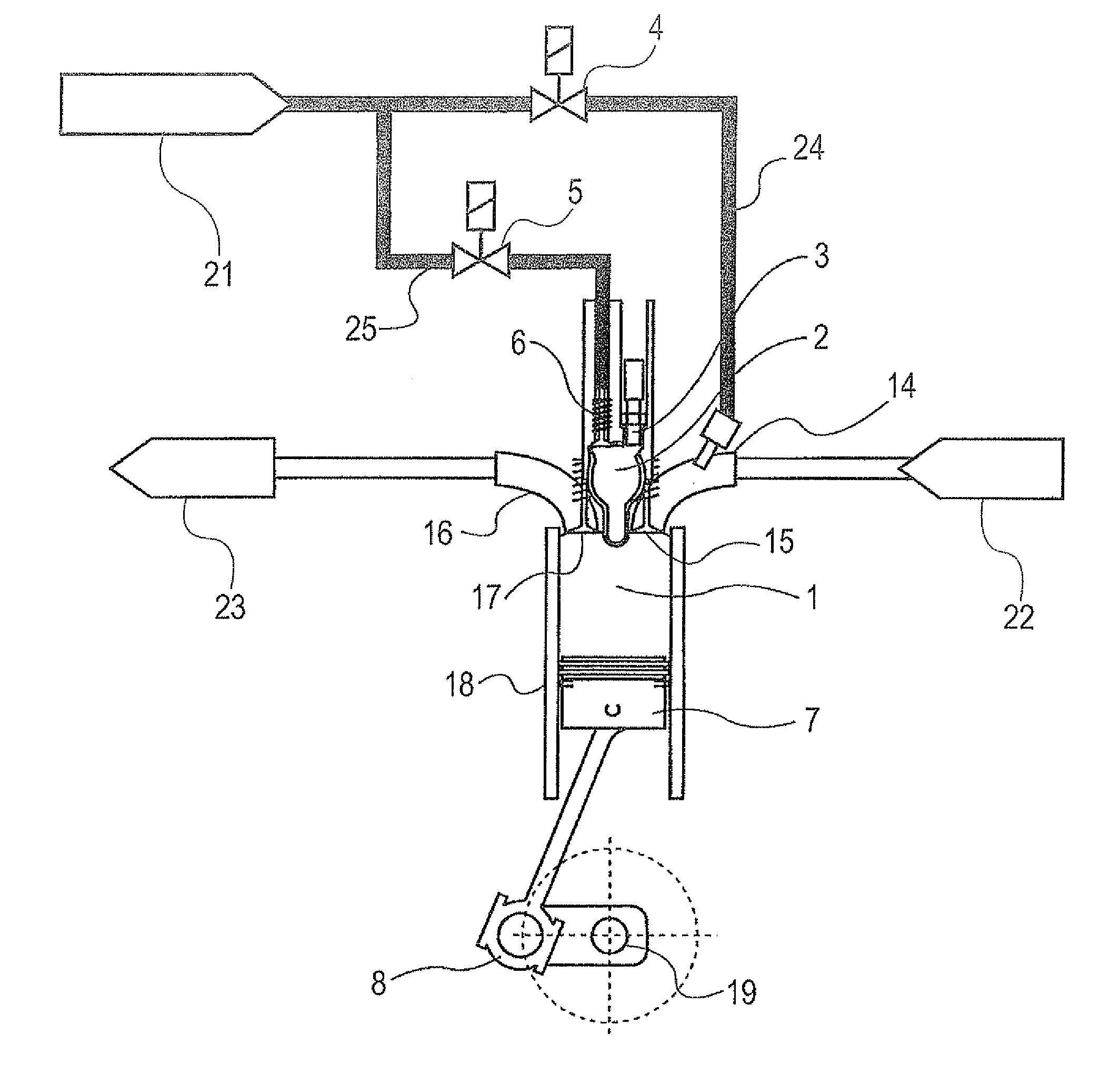
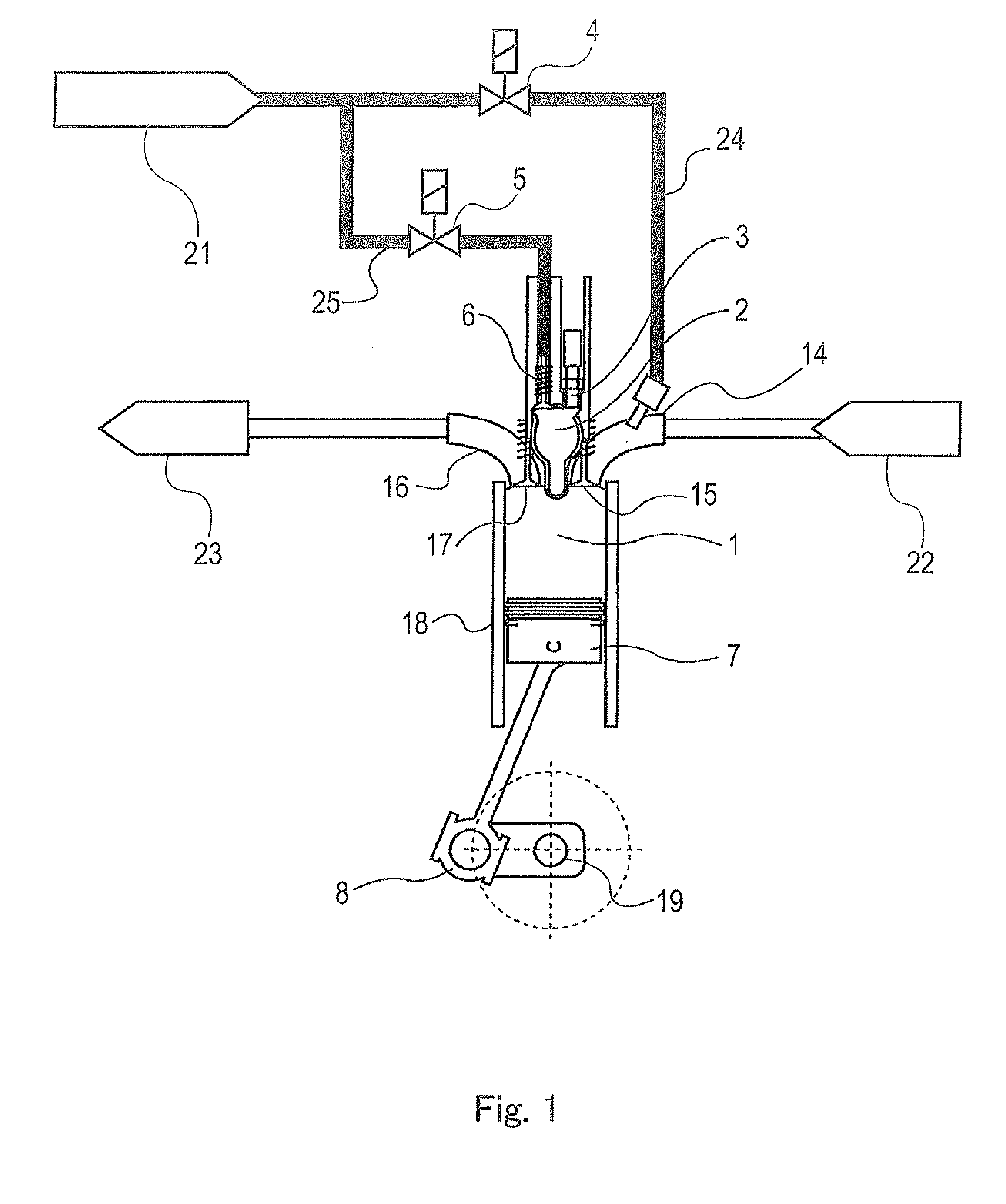
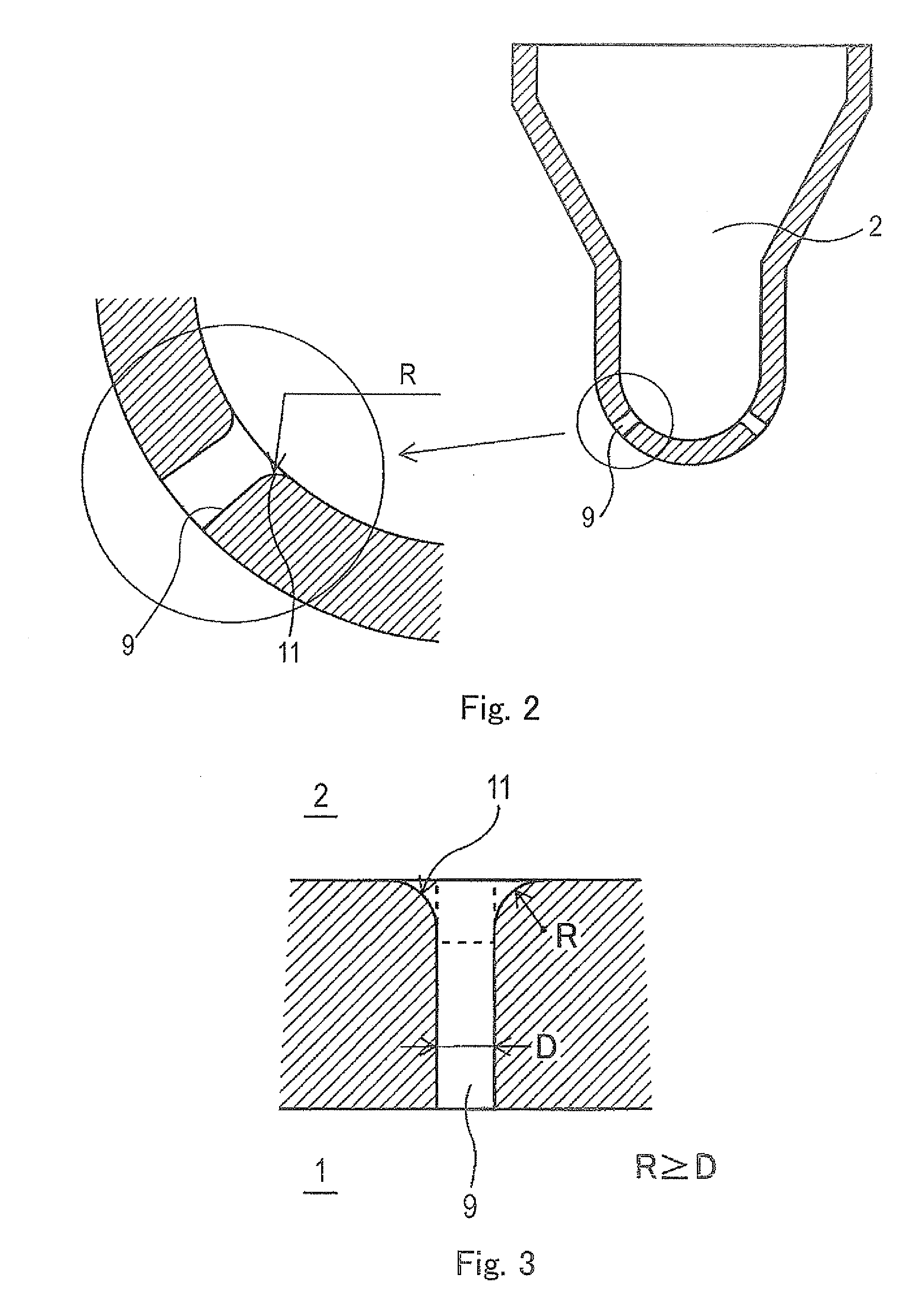
[0032]Hereinafter, one embodiment of a divided-chamber gas engine according to the present invention is described in detail with reference to the accompanying drawings. FIG. 1 is a conceptual diagram showing a structure of the divided-chamber gas engine according to the embodiment of the present invention. As shown in FIG. 1, the divided-chamber gas engine according to the present embodiment includes a two-stage combustion chamber including a main combustion chamber (which may be hereinafter referred to as a “main chamber”) 1 and an auxiliary combustion chamber (which may be hereinafter referred to as an “auxiliary chamber”) 2 connected to the main chamber 1 via a plurality of nozzles 9. The divided-chamber gas engine is a gas engine configured to perform so-called two-stage combustion, in which a lean air-fuel mixture, i.e., a fuel, supplied into the main chamber 1 is ignited by high-temperature jet flames that jet out from the auxiliary chamber 2 through the nozzles 9.

[0033]The ma...


PUM


Abstract

A gas engine is configured to inject a combustion gas from an auxiliary combustion chamber through a plurality of nozzles, through which the auxiliary combustion chamber and a main combustion chamber are in communication with each other, so as to ignite a fuel in the main combustion chamber. An opening edge, at the auxiliary combustion chamber side, of each of the plurality of nozzles is formed to have a curved surface. This structure makes it possible to maintain stable combustion in the main combustion chamber while preventing degradation in combustion performance.

Description

TECHNICAL FIELD[0001]The present invention relates to a divided-chamber gas engine including an auxiliary combustion chamber (an auxiliary chamber), and particularly to nozzles (nozzle holes) through which a combustion gas is injected from the auxiliary combustion chamber of the gas engine into a main combustion chamber.BACKGROUND ART[0002]Divided-chamber gas engines include a main combustion chamber (which may be hereinafter referred to as a “main chamber”) and an auxiliary combustion chamber (which may be hereinafter referred to as an “auxiliary chamber”) connected to the main combustion chamber via nozzles. A lean air-fuel mixture (a fuel gas) is supplied to the main chamber through an air supply valve. The lean air-fuel mixture is produced by mixing a gaseous fuel and supplied air. The lean air-fuel mixture is such that air that is greater in amount than a theoretical air requirement is mixed into the fuel. Accordingly, the excess air ratio λ of the lean air-fuel mixture is high...

Claims


Application Information

Patent Timeline
Patent Type & Authority Applications(United States)
IPC IPC(8): F02B19/00
CPCF02B19/1023F02B19/108Y02T10/125F02B19/16F02B19/18F02B19/12Y02T10/12
Inventor TOKUOKA, TETSUOISHII, HIROYOSHI
Owner KAWASAKI HEAVY IND LTD
Why Eureka
Try Eureka