Pivoting panel for aircraft, and composite support piece

a composite support and aircraft technology, applied in aircraft floors, wing adjustment, air braking surfaces, etc., can solve the problems of heavy prior art solutions, difficult to secure the actuator connection fitting firmly to the panel, and the panel and the actuator are subject to extremely high forces, so as to achieve greater distance between the hinges

Inactive Publication Date: 2009-12-15
PATRIA AEROSTRUCTURES
View PDF31 Cites 17 Cited by
  • Summary
  • Abstract
  • Description
  • Claims
  • Application Information

AI Technical Summary

Benefits of technology

[0010]An advantage of the invention is that the extension portion can distribute the forces and the strain acting on the actuator connection fitting to a wide panel surface area.
[0018]An essential idea of an embodiment of the invention is that the distance between the second ends of the branches is greater than that between the first ends of the branches, the branches being diagonally tilted away from each other. This allows the distance between the hinges to be made greater, which is advantageous to panel support. Further, between the branches is left a free space that can be used for example when the support piece and the surface plates are to be fastened to each other.

Problems solved by technology

Since panels often have a relatively large surface area and since the speed of an aircraft in operation is high, the panel and the actuator are subjected to extremely high forces.
One of the problems relating to pivoting panels is how to connect the actuator and the panel to each other.
An actuator connection fitting is difficult to secure firmly to the panel.
Prior art solutions are heavy and their use in connection with panels made of composite materials is problematic.

Method used


Image

  • Pivoting panel for aircraft, and composite support piece
  • Pivoting panel for aircraft, and composite support piece
  • Pivoting panel for aircraft, and composite support piece

Examples


Embodiment Construction

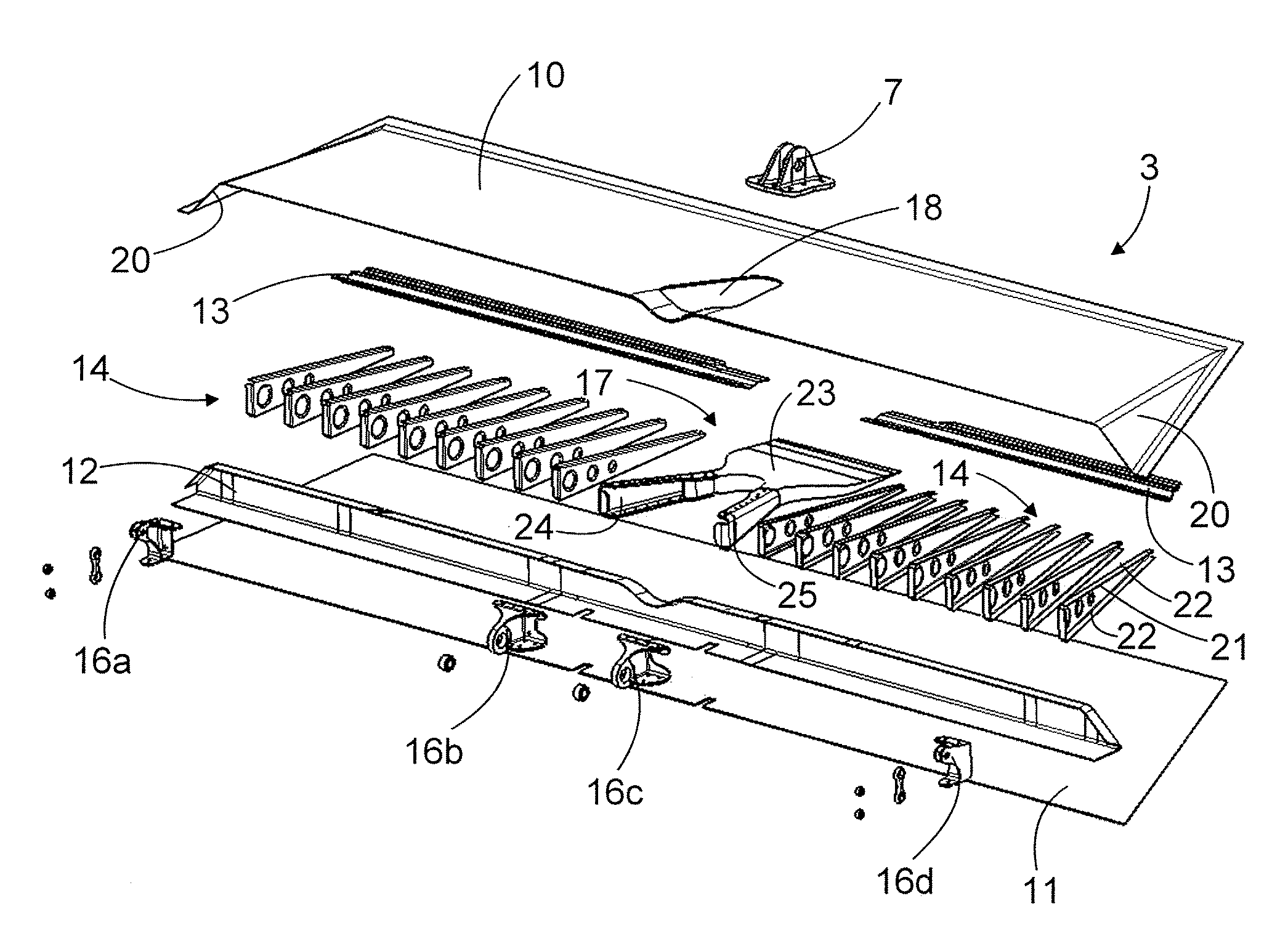
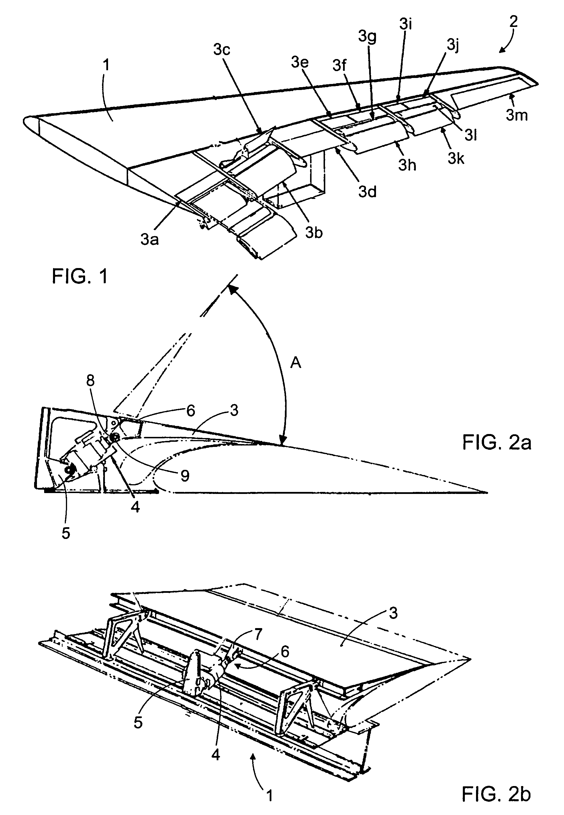
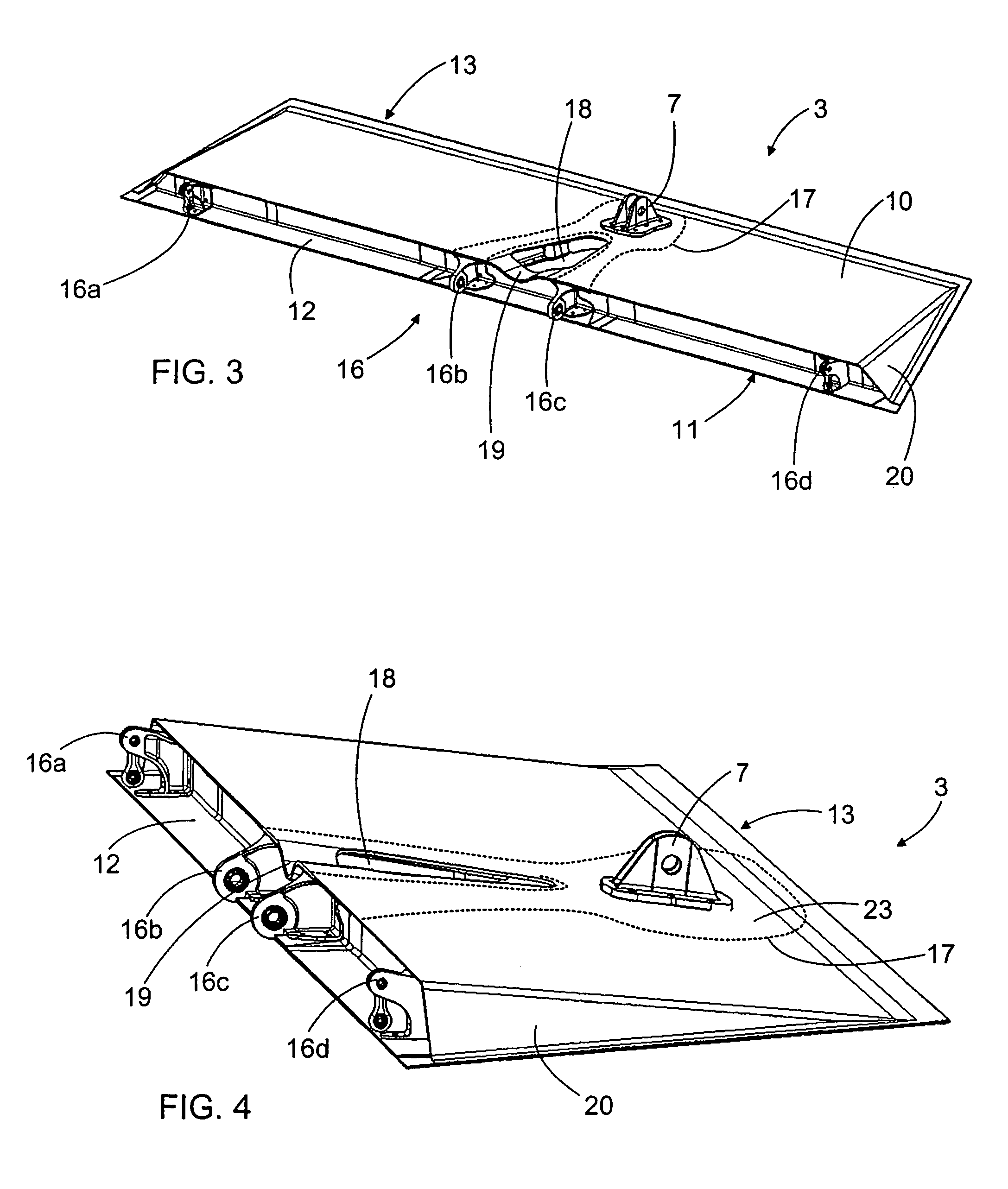
[0039]FIG. 1 shows an aircraft wing 1 and different kinds of pivoting panels 3a-3m on its trailing edge 2. Any one of these panels 3 may comprise a structure of the invention.

[0040]FIGS. 2a and 2b provide a strongly simplified illustration of the moving of a pivoting panel 3 by means of an actuator 4. The actuator 4 may pivot the panel 3 in direction A shown in the Figure. The actuator 4 may be a hydraulic cylinder, for example, or any other device capable of producing a force needed for pivoting the panel 3. When necessary, a plural number of actuators 4 may be provided for one panel 3. The actuator 4 may be connected to a frame structure of the wing 1 at a first fastening point 5, for example. Further, the actuator 4 may be connected to the panel 3 at a second fastening point 6. The second fastening point 6 may comprise an actuator connection fitting 7 that has two flanges at a distance from one another, the flanges being provided with a transverse opening, whereby a fastening loo...


PUM


Abstract

A pivoting panel for an aircraft and to a composite support piece for this kind panel. The support piece (17) is arranged as a part of the frame structure of the panel (3). The support piece has an extension portion (23) to which an actuator connection fitting (7) of an actuator (4) can be fastened. The extension portion (23) distributes the forces to the structures of the panel (3).

Description

[0001]This application is a continuation of application Ser. No. 11 / 242,608 filed on Oct. 3, 2005, now abandoned claims the benefit thereof and incorporates the same by reference.BACKGROUND OF THE INVENTION[0002]The invention relates to a pivoting panel for an aircraft, comprising: a first surface plate and a second surface plate; a front spar at the front edge of the panel and a rear spar at the rear edge of the panel; a frame structure arranged into a space defined by the surface plates and the spars; at least two hinges arranged on the front edge portion of the panel; and at least one actuator connection fitting to which an actuator is connectable for pivoting the panel in relation to the hinges.[0003]The invention further relates to a composite support piece made of a polymer matrix and reinforcing fibers.[0004]Aircraft, such as airplanes and the like, are provided with different kinds of pivoting panels that can be used for directing the aircraft and for controlling different f...

Claims


Application Information

Patent Timeline
Patent Type & Authority Patents(United States)
IPC IPC(8): B64C9/00B64C3/18B64CB64C39/02
CPCB64C9/02B64C9/323B64C9/32
Inventor KALLINEN, RISTOKORPIMAKI, JANILINJAMA, JUSSIAHO-MANTILA, ANTTIAHTONEN, PENTTI
Owner PATRIA AEROSTRUCTURES
Why Eureka
Try Eureka