
Power adapter

a power adapter and plug technology, applied in the direction of electrical apparatus, connection, coupling device connection, etc., can solve the problems of other electrical devices, inconvenient use for users, etc., to avoid having an influence on the connection, simplify the assembly and disassembly process of the plug, and improve the assembly structure

Active Publication Date: 2009-12-15
CHENG UEI PRECISION IND CO LTD
View PDF10 Cites 28 Cited by
  • Summary
  • Abstract
  • Description
  • Claims
  • Application Information

AI Technical Summary

Benefits of technology

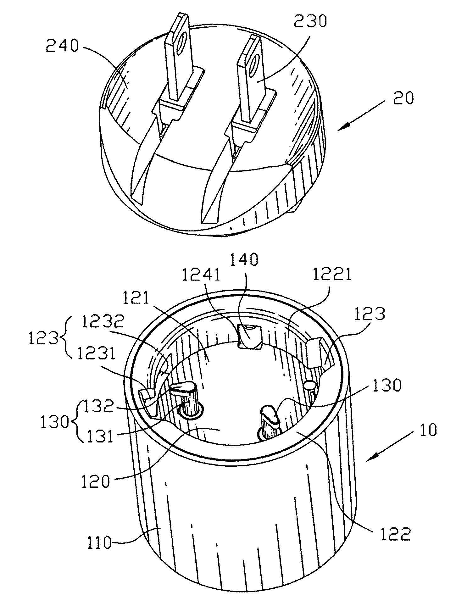
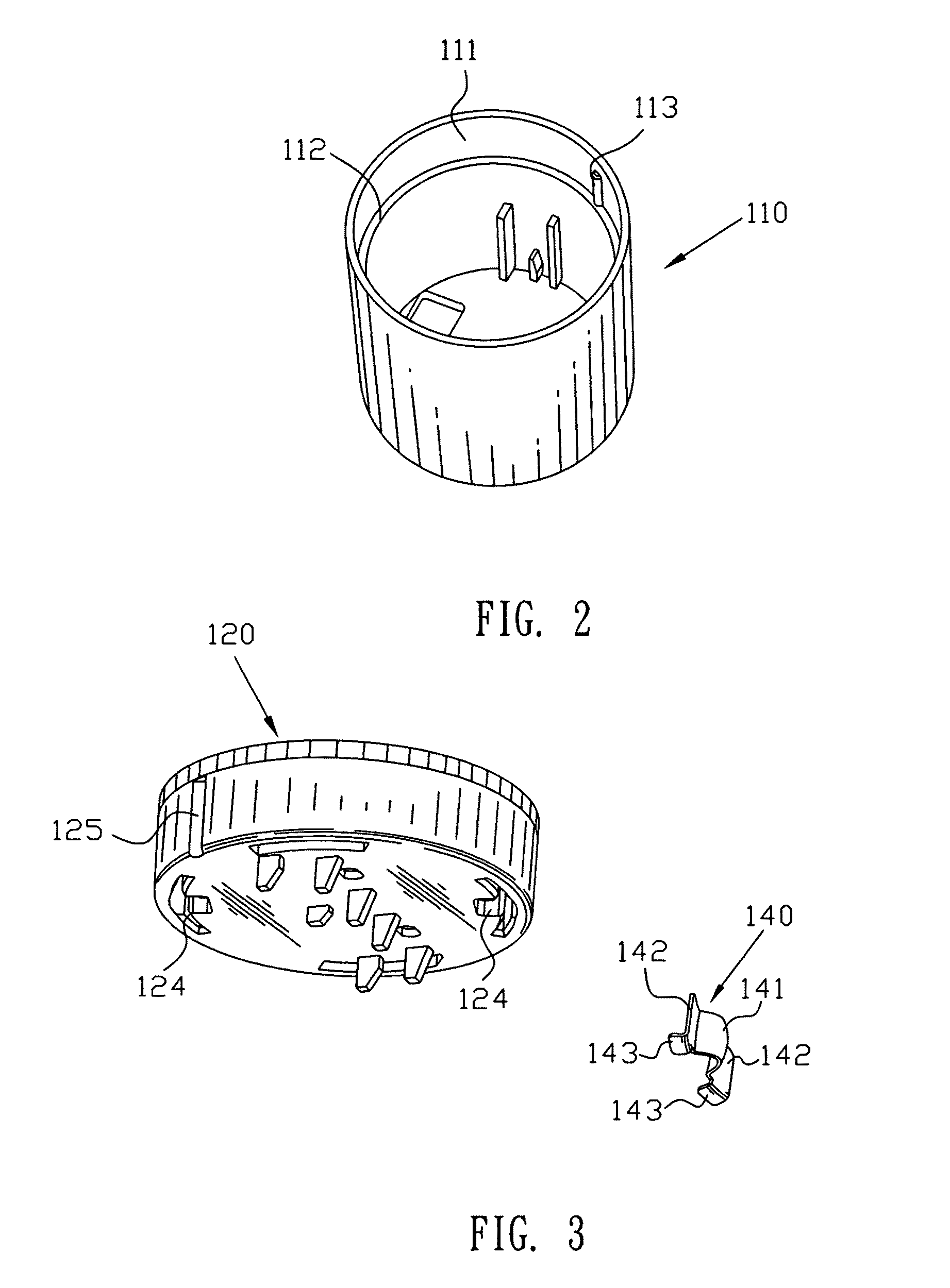
[0006]Accordingly, an object of the present invention is to provide a power adapter which has a better assembling structure for fixing a plug to a main body thereof which can simplify the process of assembly and disassembly of the plug to the main body. A top of the main body defines a recess and an annular sidewall enclosing the recess. A rotation-proof component received in the annular sidewall of the main body defines a rotation-proof portion extending into the recess. The plug is rotatably mounted in the recess, and a side of the plug defines at least one rotation-proof recess. The plug is located by rotation in the recess, then the rotation-proof portion is elastically pressed against the plug and finally the rotation-proof portion is released into the rotation-proof recess for restraining the plug from reverse rotation.
[0007]As described above, the plug is assembled to an end of the main body, the power adapter shows a pillar shape in its entirety. When the power adapter is used to connect with a socket, the power adapter occupies smaller space horizontally so as to avoid having an influence on the connection between other electrical devices and the socket. Furthermore, the power adapter is assembled by the engagement between the rotation-proof portion and the rotation-proof recess to prevent reverse rotation, which simplifies the process of assembly and disassembly of the plug with the main body.

Problems solved by technology

However, such assembling structure needs a biggish space so as to add the volume of the main body, which is not only inconvenient for user to carry the adapter during traveling, but also restrains other electrical devices from connecting with the socket when the power adapter is connected to the socket.
In additional, in assembly or disassembly, the protruding portion is necessary to be pressed down firstly so that the plug can rotate with respect to the main body, which is not quite convenient for user to use.

Method used


Image

  • Power adapter
  • Power adapter
  • Power adapter

Examples


Embodiment Construction

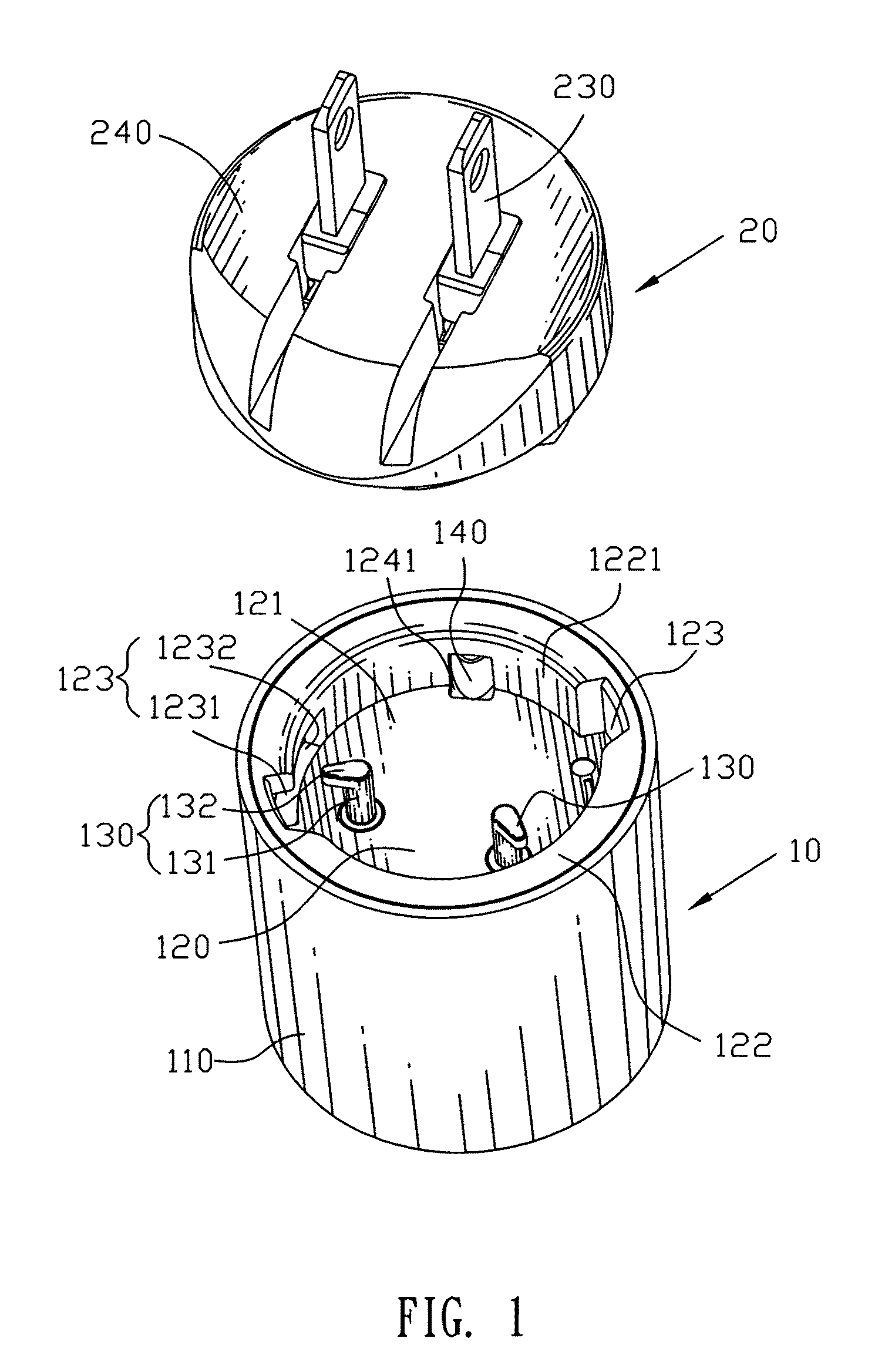
[0016]With reference to FIG. 1, a power adapter includes a case 10 and a plug 20 engaged with the case 10. The case 10 has a main shell 110, a main body 120 mounted in the main shell 110 and a plurality of main terminals 130 received in the main body 120.

[0017]Please refer to FIG. 1 and FIG. 2, the main shell 110 is cylindrical and defines an inner side 111 of circular shape. The inner side 111 has a platform 112 therearound for supporting the main body 120 thereon. An upper portion of the inner side 111 protrudes outwards (namely, protrudes toward the center of the circular inner side 111) to form at least one stopping strip 113 adjacent to the platform 112 and extended along an axis of the circular inner side 111. In this embodiment, there are two stopping strips 113 arranged diametrically symmetrically at the inner side 111.

[0018]Please refer to FIGS. 1-3, the main body 120 is of pillar (or in other word, cylindrical) shape and defines a recess 121 therein and an annular sidewall...


PUM


Abstract

A power adapter has a main body of cylindrical shape. A top of the main body defines a recess and an annular sidewall enclosing the recess. A rotation-proof component received in the annular sidewall of the main body defines a rotation-proof portion extending into the recess. A plug is rotatably mounted in the recess, and a side of the plug defines at least one rotation-proof recess. The plug is rotatably secured in the recess then the rotation-proof portion is elastically pressed against the plug and finally the rotation-proof portion is released into the rotation-proof recess for restraining the plug from reverse rotation.

Description

BACKGROUND OF THE INVENTION[0001]1. Field of the Invention[0002]The present invention relates to a power adapter, and more particularly to a power adapter which can make a plug and a main body thereof to be engaged with each other firmly.[0003]2. The Related Art[0004]Generally, a power adapter is always used for adapting different sockets provided in different countries when one traveling all over the world. Therefore, a plug of the power adapter for connecting with the socket also must be exchangeable for adapting. At present, the power adapter generally includes a main body and a plug rotatably mounted to the main body. The main body has an opening, and a side of the plug has an arm with a protruding portion located on an end thereof and away from the main body. A guiding recess in the main body is the pathway passed by the arm and the protruding portion so that the protruding portion is wedged into the opening for preventing the plug from reverse rotation.[0005]However, such asse...

Claims


Application Information

Patent Timeline
IPC IPC(8): H01R29/00
CPCH01R31/06H01R27/00H01R13/625H01R13/639
Inventor MA, JIAN-RONGWEI, HUA-HU
Owner CHENG UEI PRECISION IND CO LTD
Learn More