Compact compression connector with attached moisture seal

a compression connector and moisture seal technology, applied in the direction of couplings/cases, coupling device connections, coupling parts engagement/disengagement, etc., can solve the problems of prone to errors in both installation techniques, labor-intensive and craft-sensitive installation of present 50 ohm connectors, and reduce the diameter of the opening of the attachment element, preventing inadvertent detachment of the attachment elemen

Inactive Publication Date: 2009-12-15
PPC BROADBAND INC
View PDF66 Cites 21 Cited by
  • Summary
  • Abstract
  • Description
  • Claims
  • Application Information

AI Technical Summary

Benefits of technology

[0011]In accordance with an exemplary embodiment, a compression connector for the end of a coaxial cable comprises a connector body that has a first end, a second end, and an outer diameter. An attachment element has an opening defined therein, wherein the opening has a first, unincreased diameter less than at least a portion of the outer diameter of the connector body, and a second, increased diameter greater than at least a portion of the outer diameter of the connector body. The opening of the attachment element is placed around the connector body at a predetermined placement location while the second, increased diameter of the opening of the attachment element is substantially maintained. If desired, the predetermined placement location can have a diameter less than that of the first, unincreased diameter of the opening of the attachment element, such that once the attachment element is placed at that placement location the diameter of the attachment element will automatically revert to its first, unincreased diameter so as to prevent inadvertent detachment of the attachment element. That, in turn, prevents the loss of misplacement of a connector component (e.g., a moisture seal) that is also attached to the attachment element (e.g., at a connection zone or area).

Problems solved by technology

Present 50 ohm connectors require labor intensive and craft sensitive installation.
The connectors used in both of these approaches are relatively expensive, most notably due to their multitude of precision parts.
Furthermore, both of these installation techniques are prone to errors that may not be readily apparent to or perceived by the installer, e.g., the threaded body sections not having been fully tightened together.
A more fundamental problem, however, involves one or more of the precision parts of the connector becoming inadvertently lost or misplaced prior to or during the installation process.
When this occurs, it results in economic loss due to absorbing the cost of the lost or misplaced part(s), plus it causes non-nominal installation delays in order to identify the particular problem and to locate and install the suitable replacement part(s).
And although such installation delays can be experienced in factory and field installation settings, the resulting delays are often more impacting in a field setting since there it is less likely that a spare part will be immediately on hand.
This problem can plague nearly all cable connectors that are being currently sold and used, even those that otherwise function well.
Thus there have been reported instances in which the sealing element is lost or misplaced prior to or during installation.
And given the importance of the sealing element in providing moisture resistance, this leaves the installation technician no choice but to replace the lost / misplaced sealing element, which is not ideal, or to not install the connector assembly, which is not acceptable.
It also has been acknowledged that so-called “radial compression type” end connectors (e.g., those described in the '679 patent, U.S. Pat. No. 3,498,647 to Schroder, U.S. Pat. No. 3,985,418 to Spinner, U.S. Pat. No. 4,059,330 to Shirey, U.S. Pat. No. 4,444,453 to Kilry et al., and U.S. Pat. No. 5,024,606 to Yeh Ming-Hwa, each of which is hereby incorporated by reference in its entirety) are especially prone to suffer from this lost or misplaced connector parts problem.
Unfortunately, the solution offered by the '246 patent has its own set of shortcomings.
In particular, the process of manufacturing the connector to include the integral attachment ring and attached compression sleeve is quite complex and does not allow for much, if any, freedom with regard to how the attachment ring is attached to the connector, let alone the attachment location.

Method used


Image

  • Compact compression connector with attached moisture seal
  • Compact compression connector with attached moisture seal
  • Compact compression connector with attached moisture seal

Examples


Embodiment Construction

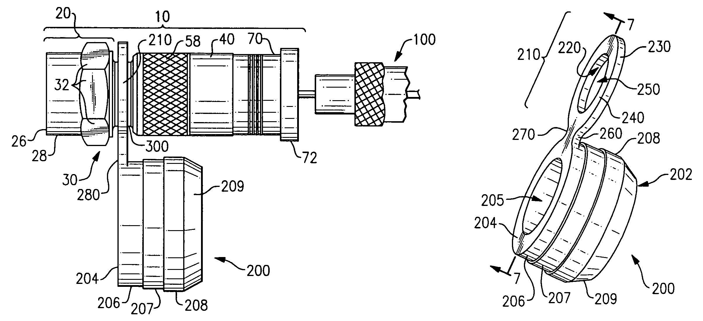
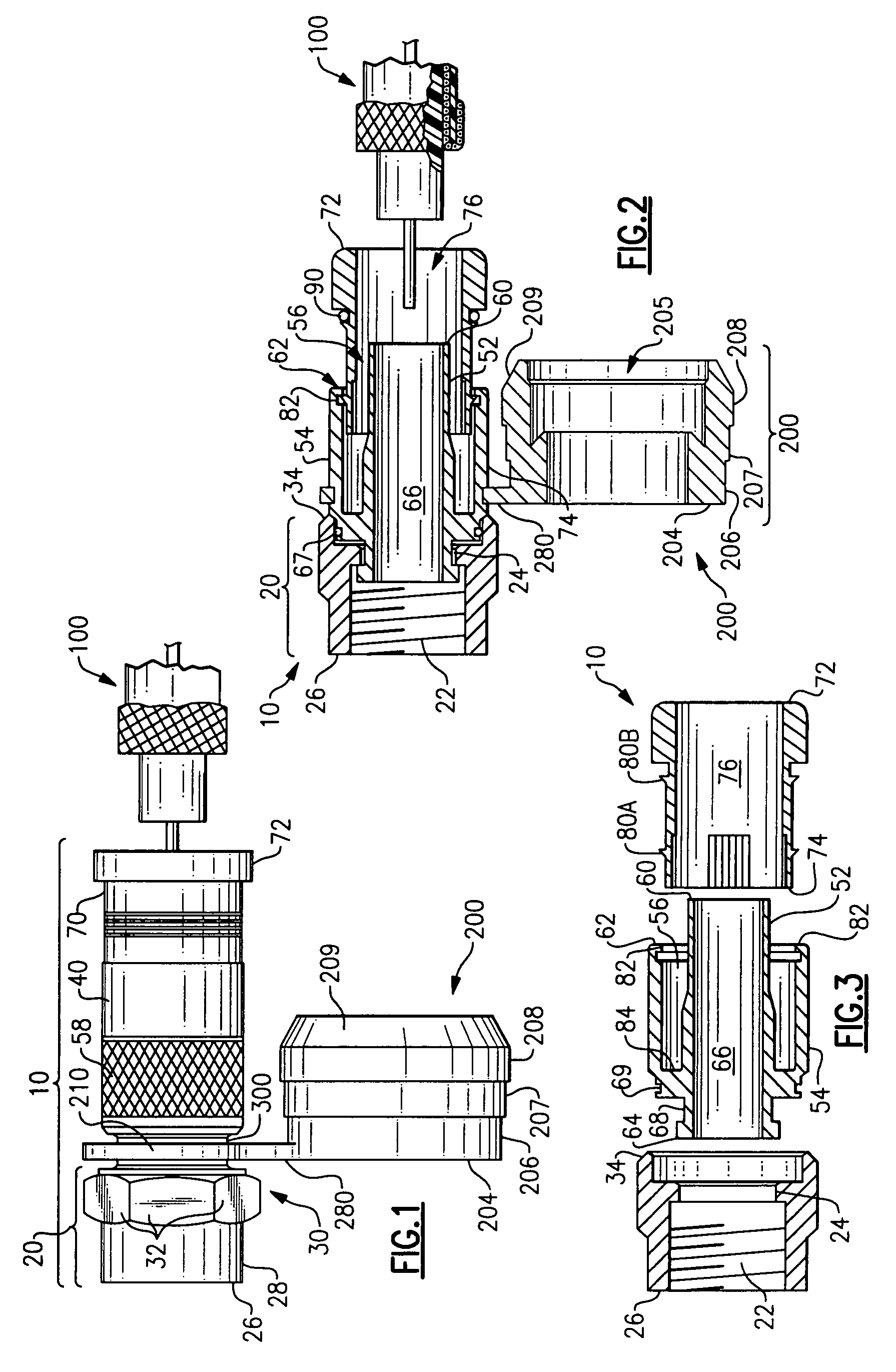
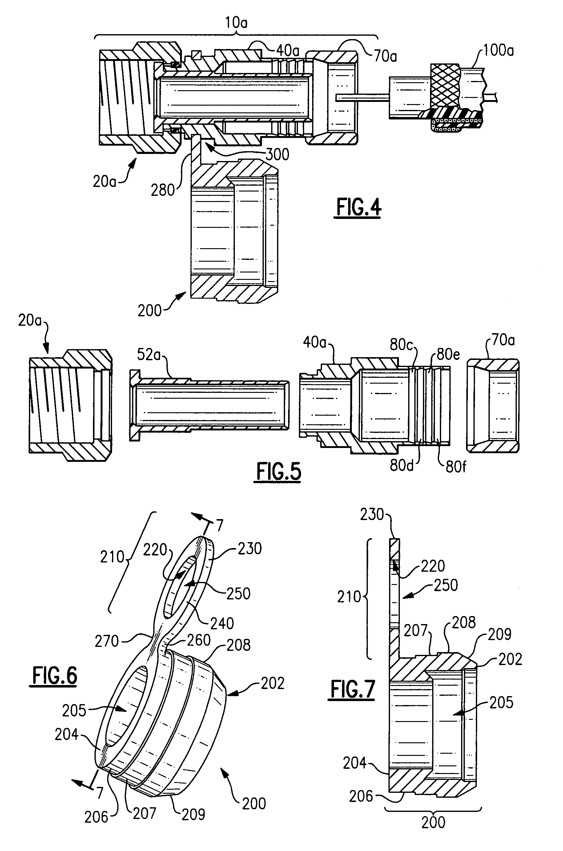
[0026]Referring initially to FIGS. 1-3, an end connector 10 for coaxial cable is shown. The connector 10 is comprised of a fastening element 20, a body portion 40, and a locking member 70, each as described below. The depicted connector 10 is a so-called internal radial compression type coaxial cable F-connector. An exemplary such connector also is shown and described in U.S. Pat. No. 5,470,257 to Szegda, which is hereby incorporated by reference in its entirely. It is understood that the concepts and features of the connector 10 depicted in FIGS. 1-3 (and in FIG. 8B) and described herein are applicable to other types of coaxial cable connectors as well, including, but not limited to, external radial compression type connectors (see connector 10a in FIGS. 4, 5 and 8A), crimped-style cable connectors (see connector 10b in FIG. 9) and threaded-style cable connectors, as well as still other types of compression connectors.

[0027]FIGS. 1 and 2 also depict a segment of cable 100 to which ...


PUM


Abstract

A compression connector for the end of a coaxial cable is provided, wherein a moisture seal element is attached to an attachment element, and wherein the attachment element is attached to, adjoined to, or otherwise placed in tactile communication with the compression connector, thus in effect placing the moisture seal in communication with the connector so as to prevent the moisture seal element from being inadvertently lost or misplaced prior to installation of the connector.

Description

FIELD OF THE INVENTION[0001]This invention relates in general to coaxial cable connectors, and, more particularly, to compression connectors for use with coaxial cables wherein at least one part (e.g., a moisture seal) of the connector is attached to, adjoined to, or otherwise in communication with the connector prior to installation of the connector.BACKGROUND OF THE INVENTION[0002]The deployment of 50 ohm coaxial cable, such as 200, 400 and 500 sizes of cable, for video and data transfer is ever increasing. Present 50 ohm connectors require labor intensive and craft sensitive installation. In one proposed approach, a 50 ohm connector is supplied as a kit and is installed onto a coaxial cable in stages, which must occur in a set order and may require soldering for proper assembly. Another proposed installation approach employs multiple threaded body sections and requires the use of multiple wrenches to draw the separate body sections together, thereby exerting a clamping force onto...

Claims


Application Information

Patent Timeline
Patent Type & Authority Patents(United States)
IPC IPC(8): H01R9/05
CPCH01R13/5219H01R9/0524H01R2103/00
Inventor MALAK, STEPHEN
Owner PPC BROADBAND INC
Why Eureka
Try Eureka